Ramp Replacement
About
This procedure provides instruction to remove and install the Ramp Assembly.
Specifications
| System Component | Specification |
|---|---|
| Ramp Pivot Hinge Bolts | 1080 in-lbs (90 ft-lbs or 122 Nm) |
| Ramp-Yoke Fasteners | 330 in-lbs (27.5 ft-lbs or 37.2 Nm) |
| Ramp Cover Mounting Clip Screws | 30 in-lbs (3.4 Nm) |
Procedure
Review entire procedure before starting.
Removal Instructions
- Access the service menu diagnostic CrossRamp Test and set the incline level to 15
- P10, P30, P30i and P31: (Service menu (51765761) > MACHINE TEST > CROSSRAMP TEST and raise the INCLINE LEVEL to 15).
- P62, P80, and P82: (Service menu (51765761) > System Settings > System Tests > CrossRamp Test and raise the INCLINE level to 15).
|
|
CAUTION: If there is an active lift error code (E40, E42, E45, or E46), be careful to not jam the ramp when raising or lowering the ramp in CROSSRAMP TEST. There are no software position limit stops when operating in CROSSRAMP TEST. |
- Disconnect either the battery negative terminal or the Lift Motor input power/control cable.
|
|
WARNING: Make sure to disconnect the Lift Motor input power/control cable or it is possible for the crossramp to automatically lower to the default level 1 if either the pedal arms are moved or the CrossRamp Test is exited. This unexpected action could cause personal injury. |
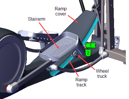
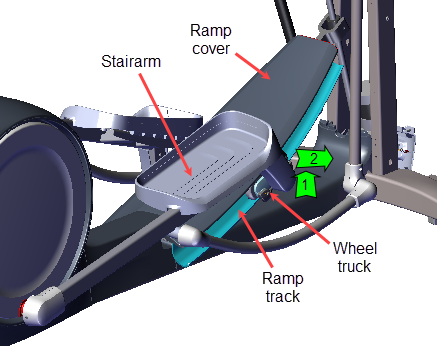
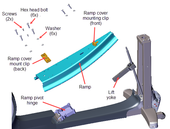
- Remove the Stairarm wheel truck assemble from the ramp track and lay the Stairarm on the floor. To remove, grasp the bottom of the wheel truck assembly and lift up and outward from the track. No tools or fastener removal is required. It may help to lift the outer edge of the CrossRamp cover while removing.
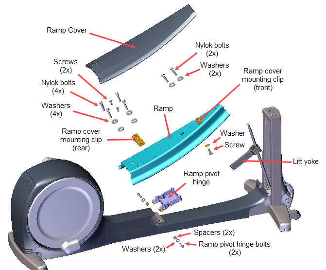
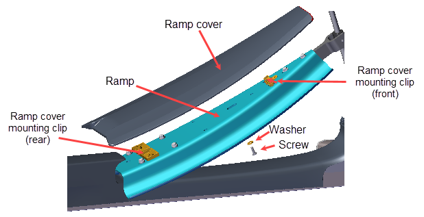
- Use a short stub #3 screwdriver to remove the one screw and washer that secures the Ramp cover and remove. Retain part(s) and/or fastener(s) for installation.
- Remove the ramp hinge fasteners:
- Remove the four 9/16" bolts (4x) and washers (4x) that secure the ramp to the ramp pivot hinge. Retain part(s) and/or fastener(s) for installation.
- Remove the two #2 Phillips screws that secure the back ramp cover mounting clip to the ramp pivot hinge. Retain part(s) and/or fastener(s) for installation.
- Remove the two 9/16" bolts (2x) and washers (2x) that secure the ramp to the lift yoke and remove the ramp. Take care to hold the ramp while removing the fasteners because the ramp will fall from the yoke when the fasteners are removed. Retain part(s) and/or fastener(s) for installation.
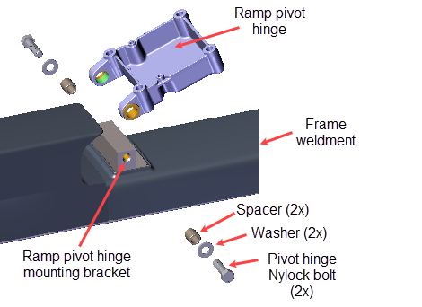
- Remove the left and right 3/4" (19 mm) ramp pivot hinge Nylock bolts (2x), flat washers (2x), spacers (2x) and remove the Ramp Pivot Hinge. Discard the pivot hinge Nylock bolts and retain the flat washers.
|
|
CAUTION: Do not reuse the Ramp Pivot Hinge Nylock patch bolts for installation. Discard the used bolts and order new bolts for installation (see Exploded View Diagrams, bubble # 361). |
Installation Instructions
Ramp Pivot hinge Installation
- Position the Ramp Pivot hinge onto the frame weldment ramp pivot hinge mounting bracket and secure using New left and right 3/4" (19 mm) ramp pivot hinge Nylock bolts (2x), flat washers (2x), spacers (2x). TorqueTorque is a measure of the force that can cause an object to rotate about an axis. Bolt/nut example: 5 nM torque is equivalent to 5 newtons of force applied one meter from the center of the bolt, 6 ft-lb is equivalent to 6 lb of force applied 1 foot away from the center of the bolt. bolts to 1080 in-lbs (90 ft-lbs or 122 Nm).
|
|
CAUTION: Do not reuse the Ramp Pivot Hinge Nylock patch bolts for installation. Discard the used bolts and order new bolts for installation (see Exploded View Diagrams, bubble # 361). |
- Position the ramp onto the lift yoke and ramp pivot hinge. Align the two ramp yoke bolt holes and secure using two 9/16" hex head bolts (2x) and washers (2x). Torque bolts to 330 in-lbs (27.5 ft-lbs or 37.2 Nm).
- Reinstall the ramp onto the ramp pivot hinge.
- Place the ramp cover mounting clip onto the ramp. Then set the ramp onto the ramp pivot hinge aligning the two ramp cover mounting clip bolt holes. Secure using the two #2 Phillips screws. Do not over tighten the screws, torque to 30 in-lbs (3.4 Nm).
- Finish securing the ramp to the ramp pivot hinge using the four 9/16" bolts (4x) and washers (4x), torque bolts to 1080 in-lbs (90 ft-lbs or 122 Nm).
- Preparing the Ramp wheel tracks:
- Use a clean rag and approved cleaner (see Cleaning Procedure) to clean both wheel tracks. Clean any hard-to-remove grime using a Scotch-Bright pad (or fine steel wool). Dry ramp track surfaces with a clean rag.
- Apply a thin coat of Swix UR10 Yellow Bio Racing ski wax (or equivalent) to the wheel contact area of the ramp wheel tracks. Rub the wax back and forth across the length of the track several times. Ski wax is preferred to oil based lubricants because ski wax is less prone to attract dust and dirt.
Gently wipe away any excess wax with a clean rag.
- Reinstall the Ramp cover and use a short stub #3 screwdriver to secure the screw and washer to the ramp. Do not over tighten the screw, torque to 30 in-lbs (3.4 Nm).
- Use an approved cleaner (see Cleaning Procedure) to clean the left and right Stairarm wheels. Dry with a clean cloth.
- Reinstall the left and right Stairarm wheel trucks onto the Ramp tracks. To install, insert the top of the wheels underneath the outer edge of the Ramp cover while lifting the bottom of the wheels into the Ramp track. You may need to slightly lift up the outer edge of the Ramp cover while inserting the wheels into the track.
- Reconnect the Lift Motor input power/control cable and/or the battery negative/positive terminals if disconnected.
-
Do a QUICKSTART workout and operate the elliptical at INCLINE level 1 and RESISTANCE level 1 at 130 strides per minute for two minutes, or longer, to break-in the wax and verify operation. While operating the machine, listen for wheel squeak or other unusual noises:
- If there were wheel squeaking or unusual noises, visually inspect the Ramp tracks to confirm wax coverage across the entire wheel contact path. If not, reapply the wax and repeat the wax break-in operation.
- At the completion of the wax break-in, gently wipe away any excess wax with a clean rag.
- Verify machine operation and return to service, see Operation Verification.
Ramp Installation