Theory of Operation
About
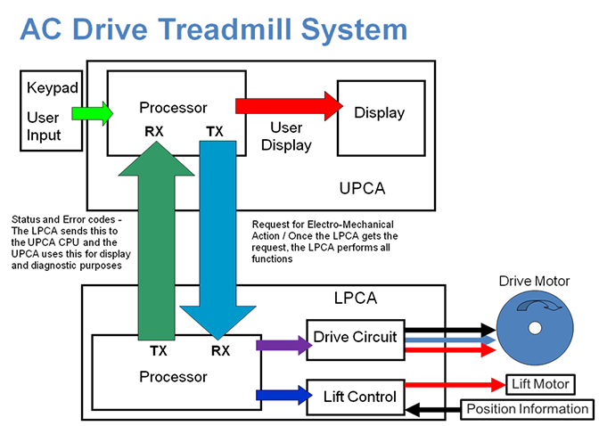
The treadmill is comprised of two basic system blocks, the console provides the user interface and operational controls. It contains the Upper PCAUpper printed circuit assembly; generally refers to the console. board which sends the control input information to the base. The base contains and uses the Lower PCALower printed circuit assembly; generally this refers to the lower board. On treadmills, this is the motor controller unit (MCU), and on self-powered units, it is the main board in the lower section. board to execute received operational commands. The Lower PCAPrinted circuit assembly, generally referred to as either an upper PCA or lower PCA. returns status and error code information to the Upper PCA for display and diagnostics.
Console Operation
This section will explain basic operation and functions that apply to all models of consoles. For specific details about a particular model of console (Standard, P10, P20, P30, P80), refer to the applicable console service manual.
The supported console models include the P10, P20, P30, P80, and P82 models.
Controls
All consoles provide user input (keypad functions), user display (LED display / user feedback), automated control (heart rate program, interval program) and service software routines (tests, settings, and information).
The keypad functions can vary between different console models, however the basic functions that all consoles have include the Quick Start, Incline (up or down) and Speed (up or down) functions.
Features
Different console models provide a different set of user features but the basic operation and servicing software is the dame.
The service software functions exactly the same for all console models. Each console uses the same service software standard access codes to access the Hardware Validation Tests, Club Parameter settings, or Information Display modes, see .
The service software also utilizes the same Standard Error Codes in all console models, see .
The console processor (upper PCA board "UPCAUpper PCA board") provides user input, user display and automated control to the system. The console processor communicates with the base processor (Lower PCA "LPCALower printed circuit assembly; generally this refers to the lower board. On treadmills, this is the motor controller unit (MCU), and on self-powered units, it is the main board in the lower section.") which then performs the actual machine function.
The two processors communicate via a serial data stream. When the user makes a request via a machine control or the keypad, the console processor communicates the command to the processor in the lower electronics module.
When the lower processor receives a command the lower control module performs the machine function. The console processor continues to monitor machine controls, keypad entry, lower board status, and provide user feedback information.
The lower board base processor also provides machine operation and error status (error log codes) to the console processor.
Treadmill Base Operation
The GEN-06 / TRM10TRM800 version 1 treadmills mfg. dates 2010 thru 2014. base is equipped with a removable line cord plugged into a power entry socket. This is designed to accommodate either 120 VACvoltage in an alternating current circuit or 240 VAC NEMA compatible line cords, as well as line cords for other countries. The diagram below shows a NEMA 20A plug for both 120 VAC and 240 VAC configurations in the United States.

|
|
CAUTION: The treadmill requires a 20-amp individual branch circuit grounded per NEC (National Electric Code) guidelines or local region electric code. |
120 VAC power, when measured from hot to neutral, should read between 90 and 10’s. ’40s power, when measured from hot to neutral should read between 180 and 264 VAC. This input voltage is applied through the power entry plug and wired to the breaker switch. The 120 VAC breaker switch only interrupts the hot line and the 240 VAC breaker switch interrupts both the hot and neutral lines. The power is then fed through a line filter which removes high frequency noise from the line voltage. After the power is cleaned by the line filter it can be applied to the lower electronics module (IFTIntegrated Footplant Technology: IFT recognize this change in speed when your foot strikes the belt and adjust to match every stride, resulting in a smooth, fluid feel that enhances the workout experience. drive).
Review electrical requirements, see >Electrical Requirements.
The lower control module consists of an ACAlternating Current: electric current which periodically reverses direction between positive and negative polarity. drive motor controller, an AC lift motor controller and a +8.5 Vdc power supply to power the console.
The electronic circuits in the console operate on +5 Vdc, however the lower control module sends +8.5 Vdc due to the optional external equipment such as Fitlinxx products connected to the CSAFECommunication Specification for Fitness Equipment protocol. (communication standard for all fitness equipment) port. Sending a higher voltage (+8.5 Vdc) and regulating the voltage down to +5 Vdc ensures enough supply power to support both the console and the optional external equipment.
It is important to note that the lower control module (IFT module) has different part numbers for the 120 Vac unit the 240 Vac treadmill.
The AC drive system controls the three phase AC drive motor. In an AC motor, speed is controlled by frequency independent of voltage or current, torque is controlled by the voltage/current applied to the motor 3 phase windings. The windings (stator) and rotor core of the motor are designed to spin at a specific speed at the design frequency. The lower control module generates the correct frequency to drive the motor at the command speed. Since the speed of an AC motor is controlled by frequency, there is no need for a speed sensor.
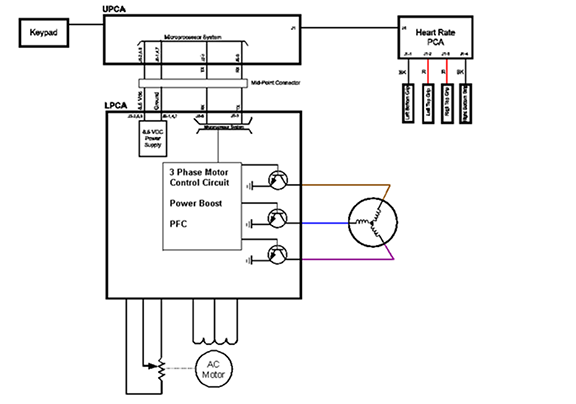
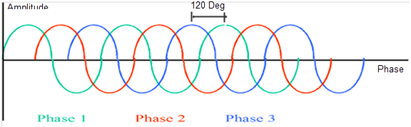
The 3 phase AC motor generates enough torque to provide continuous duty run time. The 3 phase voltage amplitude of all three input AC sine waves is the same at any given time which allows the torque to be applied smoothly throughout the rotation of the motor. Increasing the input voltage/current amplitude increases the torque and decreasing the input amplitude decreases the torque.
The lower electronics module (IFT drive) is responsible for sending the proper frequency to control speed and the amplitude (same on all 3 phases) to control torque. The motor must then be balanced both mechanically and electrically in order to translate the frequency and amplitude into fluid motion. Mechanical balance is achieved by balancing the weight of the flywheel, and electrical balance is achieved by having the same winding resistance on all 3 phase windings.
Other AC drive motor controller features include "Dynamic Braking" and "Power Factor Correction". Dynamic Braking addresses an issue where an over-speed condition could occur. If a heavy user runs at a high incline, the weight of the user has the potential to push the running belt to go faster than the commanded motor controller speed (generates excess current). The dynamic brake circuit senses the load variations and applies a braking force within the motor. The system utilizes an external power resistor (Dynamic Brake resistor) to absorb the excess generated current and determine applied braking force. Power Factor Correction is a feature that attempts to reduce power consumption. The system monitors that this power factor is held within certain parameters. If it falls outside those parameters (the system is using more current than expected), the system will flag an ERROR 29.
The Auto Stop feature monitors up and down movement of the deck. The deck motion indicates a user is present. The lack of motion indicates that a user is not present. If the running belt is moving and the Auto Stop does not detect motion from the running deck, the Auto Stop feature will stop the motion of the running belt.
GEN 06 treadmills (Mfg. date: April 2006 to April 2011) do not support the auto-stop feature. TRM10 treadmills (Mfg. date: April 2011 and later) do support the auto-stop feature.
The auto-stop feature consists of a magnet mounted on the edge of the deck, the sensor mounted on the roller mounting bracket and a cable connecting Auto-stop to the console. When a user is running on the deck, it causes the magnet to be in motion relative to the sensor. When a program is entered, Quick Start is pressed or the treadmill has been resumed after being paused, the treadmill starts at 1 mph. The user will then have 60 seconds to enter any remaining workout settings before motion detection begins. Once motion detection has commenced and if no or very little motion is detected, the Auto Stop feature interprets that the treadmill is no longer in use. The Auto Stop feature will continue to monitor the treadmill for motion for 30 seconds; if motion is still not detected a 10 second count down will be displayed on the console. After the 10 second count down has elapsed and motion has not been detected, the Auto Stop feature will stop the motion of the running belt and go into pause mode. If motion is detected within the 10 second count down cycles the shutdown feature will be aborted.
The Auto Stop feature can be enabled or disabled within the service software Club Parameters, see .
|
|
NOTE: When Auto Stop is enabled, running belt adjustment and tracking procedures should be performed in the Hardware Validation – Belt Speed Test because the Auto-Stop feature is not active during the Belt Speed Test, see |
Motion Control
The motor used in the incline system is a "Permanent Split Capacitance", single phase AC motor. The motor incorporates the use of a capacitor to provide the required lift torque. Power to the lift motor is provided directly from the treadmill AC input power.
In order to turn the motor in forward and reverse directions, the AC motor has 2 separate windings, one for up and one for down direction. The AC-1 input has a continuous connection to the center / common connection of the motor winding.
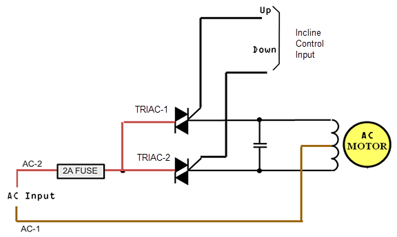
The system has a 2A fuse to protect the components from over-current failure.
When a control signal is applied to the "UP" input, TRIAC-1 control line is active and turns on the up triac. This directs the AC-2 connection to the up winding of the motor, causing the motor to spin in the up direction.
When a control signal is applied to the "DOWN" input, TRIAC-2 control line is active, turns on the down triac. This directs the AC2 connection to the down winding of the motor, causing the motor to spin in the down direction.
Since the lift motor runs directly on the AC input voltage, it is important to note that there is a different part number for a 120 Vac unit and a 240 Vac unit.
Position Monitoring
The unit also requires an absolute measurement of lift position. This is achieved through the use of a potentiometer. The potentiometer resistance wiper is turned by gears in the lift motor.
With +3. 3 Vdc is applied across the potentiometer, the center wiper connection will create a variable voltage between 0 and +3. 3 Vdc representing the position of the lift or incline. This variable voltage is applied to the input of a 16-bit A/D converter which converts the analog voltage into a 16-bit binary numeric representation that the processor can understand.
As the potentiometer voltage changes between 0 and 3. 3 Vdc, the corresponding A/D values change between 0 and 65507. The processor uses the A/D number to track the lift position.
It is important to note that since the potentiometer is mechanically connected to the internal gearing of the motor, it would be highly unlikely for a lift motor to go out of calibration without having physical damage to the potentiometer mechanism.
See Also