Auto Stop Troubleshooting
This procedure will provide troubleshooting steps for the Auto Stop feature
Related Error Codes
Auto Stop error codes: 60, 61.
Refer to the Error Code Troubleshooting Guide for error code description and troubleshooting information.
Procedure:
- If the Console message is "Temporarily Out of Order" on the P80 console or "Please use another Treadmill" on the P10, P20, or P30 console go Run Hardware Validation Tests below.
- Check the treadmill to ensure the Auto Stop hardware is installed.
- If the Auto Stop hardware is not installed, contact Precor customer support to see if your treadmill is compatible for the Auto Stop or arrange the installation of the Auto Stop hardware.
- Verify that the Auto Stop cable is plugged into the correct port in the console. The connector for the Auto Stop is the same number of pins as the connector for the heart rate grips, and you need to make sure that they were not reversed.
- If the cables were reversed, swap the connectors and re-test.
- If the cables were correctly connected, continue
- If the Auto Stop hardware is installed, access the club settings and check if the Auto Stop feature is enabled. If it is not enabled, enable the feature, see .
- Access the service access software Hardware Validation Tests (see and select the Auto Stop test. If the feature is enabled the P80 Auto Stop sensor test will count the number of times the magnet crosses the sensor. The P10, P20, or P30 consoles will display USER DETECTED if motion is detected from the running deck or NO USER DETECTED if no motion is detected from the running deck. If the unit passes this test or a USER DETECTED message is displayed and the Auto Stop feature does not function contact Precor Customer Support. If the Auto Stop did not pass the test continue troubleshooting.
Run Hardware Validation Tests
|
|
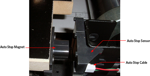
CAUTION: Do not place the Auto Stop Magnet on or near a steel structure. If the magnet assembly comes in contact with a steel structure and then pulled away from the steel structure, the magnet can become dislodged from the magnet assembly housing. Contact PRECOR customer service for repair or replacement. |
- The Auto Stop system consists of a magnet holder mounted to the right front corner of the deck and a Hall Effect sensor mounted to the drive roller bracket of the frame. Check the alignment and gap (3/16") between the Auto Stop magnet holder and the Auto Stop sensor. If the alignment and gap are not correct, it may be necessary to loosen the deck and adjust so that the magnet is gaped and positioned properly relative to the sensor. Reference Procedure, Replacing the Auto Stop Magnet. If the alignment and the gap between the Auto Stop magnet holder and the Auto Stop sensor are correct continue with step 9.
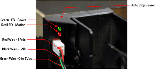
- The Auto Stop sensor will display a green blinking LED visible next to the connector, indicating that power is being applied to the sensor board. The LED does not tell you if the voltage is correct, just that it is present. If the LED is not lit or if LED is lit continue with the next step.
- The connector has 3 wires (red, black, and green), which can be metered for troubleshooting. Unplug the Auto Stop connector from the Auto Stop Sensor.
- Place the meter red lead to the red wire and black lead to the black wire of the Auto Stop connector. The meter should indicate 5 volts +/- 0.1 volt. If 5 volts is present continue with the next step.
- If the 5 volts is not present of significantly low temporarily replace the Auto Stop cable with a known good cable and repeat step 10. If the 5 volts is not present or the voltage is still significantly low replace the console or upper PCAPrinted circuit assembly, generally referred to as either an upper PCA or lower PCA.. If 5 volts is present permanently replace the Auto Stop cable.
|
|
NOTE: The running belt does not need to be moving for this test. |
- With the Auto Stop connector plugged into the Auto Stop sensor place the meter red lead to the green wire and black lead to the black wire. The meter should indicate 5 volts +/- 0.1volt. While monitoring this voltage, have someone step onto the deck and bounce up and down. The voltage between the black and green wires should fluctuate between bounces. If the voltage does not change, replace the Auto Stop Sensor.
- If you have completed all the previous steps and Auto Stop will still not function correctly, contact Precor Customer Support.
See Also
System Troubleshooting Procedures