Drive Motor System Troubleshooting
About
This procedure applies to 3-phase drive motor systems. Occasionally, there may be issues or failures of the drive system that do not generate error codes. This procedure provides additional information to troubleshoot and repair these types of issues.
If there is a Drive Motor system error code from 20 through 29 in the error log, go to the Error Code Troubleshooting Guide, see the Error Code Troubleshooting Guide, for Troubleshooting and repair information.
If there are no errors in the error log and there are Drive Motor system related issues (such as failure to start or jittery motion) then continue with troubleshooting procedure.
Related Error Codes
Drive system error codes: 20 through 29, refer to the Error Code Troubleshooting Guide.
| RELATED ERROR CODE |
DESCRIPTION |
|---|---|
| 20 | Motor Will Not Start / No Motor Movement Detected |
| 21 | too Many Maximum Consecutive Power Requests |
| 22 | Error 22 indicates that the drive motor has been instructed to start, by either manual or program control, and the monitoring system has not received any response from the speed sensing system indicating that the drive motor has started. |
| 23 | Error 23 indicates that the speed sensor signal was lost while the treadmill was in operation. |
|
25 |
Motor Controller / LPCALower printed circuit assembly; generally this refers to the lower board. On treadmills, this is the motor controller unit (MCU), and on self-powered units, it is the main board in the lower section. Hardware Error |
|
26 |
Error 26 monitors the speed sensor signal and verifies the speed sensor signal is appropriate for the requested speed. If the speed sensor signal is incorrect or erratic an Error 26 will be displayed. |
|
27 |
motor current too high) |
|
28 |
Electronics Temperature Too High |
|
29 |
Excessive ACAlternating Current: electric current which periodically reverses direction between positive and negative polarity. Input Current |
Troubleshooting Procedure
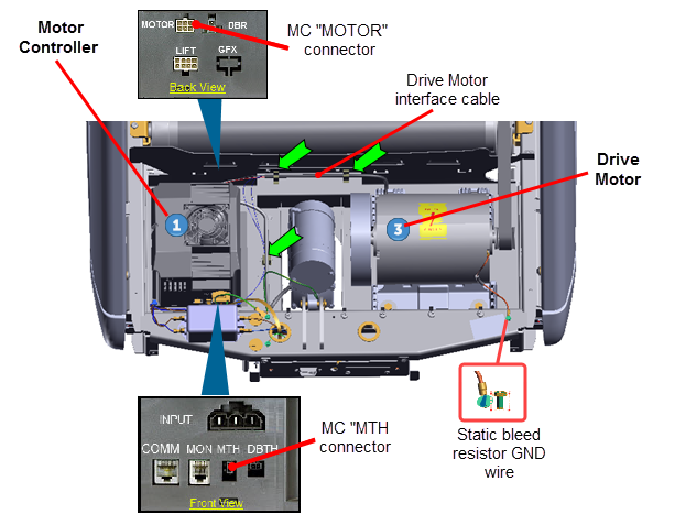
Motor Controller module "MCMotor controller or motor controller module" output power test
- Switch treadmill ON/OFF switch to OFF Disconnect the Drive Motor cable Motor connector from the Motor Controller "MOTOR" connector.
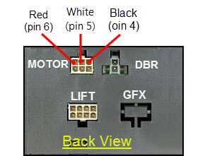
- Set the multimeter to measure AC voltage. Switch the treadmill ON/OFF switch to ON. Press the QUICK START key and immediately measure the voltage between the red wire (pin 4) & the white wire (pin 5) of the MC MOTOR connector. If the MC is supplying output power, you will momentarily (approx 2 sec) read an AC voltage value. Make a note of the voltage and switch the treadmill ON/OFF to OFF
|
|
Note: If the drive motor does not start, the Motor Controller will only apply voltage for a couple of seconds before it shuts down. Therefore the voltage readings in the following steps must be taken within the first couple of seconds after the treadmill is commanded to start the running belt. (A muftimeter with a hold feature is helpful for these measurements). |
- Repeat the AC voltage measurement between the MC MOTOR connector red wire (pin 4) & the black wire (pin 6). The measured voltage should be the approximately the same value as the previously measured red wire (pin 4) & white wire (pin 5) voltage. Set the treadmill ON/OFF switch to the OFF position.
- Repeat the AC voltage measurement between the MC MOTOR connector white wire (pin 5) & the black wire (pin 6). The measured voltage should read approximately the same value as the previously measured voltage between the red (pin 4) & black (pin 6) wires. Set the treadmill’s ON/OFF switch to the OFF position.
- If one or more of the previous MC MOTOR output voltage measurements are not present or very different, replace the MC. If the voltage measurements are approximately the same, continue the procedure.
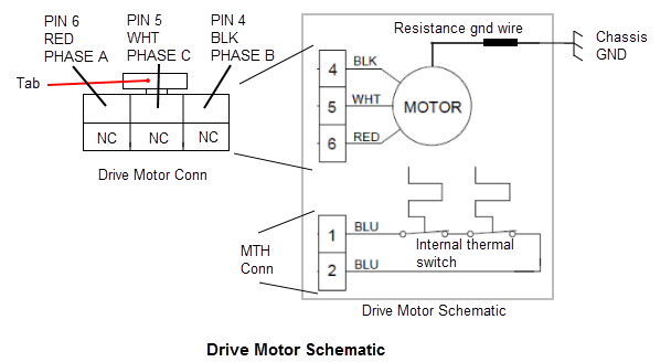
Drive motor Phase winding test
|
|
CAUTION: All resistance measurements must be performed with power removed from the machine. Performing the resistance measurements with voltage applied to the circuit can damage the multimeter. |
- Switch the treadmill ON/OFF switch to OFF. Disconnect the Drive Motor cable connector from the MC MOTOR output connector. Set the multimeter to measure resistance (ohms). Measure resistance between the Drive Motor cable MC MOTOR connector between the red wire (pin 4) & white wire ( pin 5), the red wire (pin 4) & black wire (pin 6) and the white wire (pin 5) & black wire (pin 6). Each measurement should be approximately 2.5 ohms. If any one of the measurements are significantly high (an open circuit) or zero (a short circuit), replace the Drive Motor.
|
|
CAUTION: Connector pin terminals can be easily sprung and damaged. Take care and use light probe contact pressure when making multimeter measurements. DO NOT insert large diameter probes into the plug terminals which will spring and damage the pin terminals. |
- If the Drive Motor passed the motor winding resistance test, inspect the female pins of the Drive Motor cable MC MOTOR connector. Verify that the pins are not spread apart "sprung" beyond the point of making good contact with the MC MOTOR connector male pins. If the Drive Motor connector pins are damaged, attempt to repair the connector terminals using a crimp tool for a MOLEX plug #39--01-2060 with pin terminals MOLEX #45750-3111 (recommended MOLEX pn 0457503112 crimp tool). If the connector cannot be repaired, replace the Drive Motor.
- If you have performed all of the procedures above and have been unable to correct the problem, call Precor customer support.
See Also
System Troubleshooting Procedures