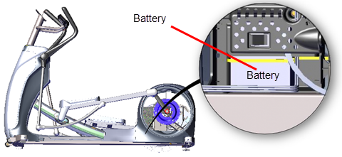
Battery Replacement
About
This procedure provides instruction to determine the condition of the battery to remove and install the Battery.
Determining the battery condition
Use the service software Hardware Validation BATTERY TEST to determine the battery condition and voltage, see Hardware Validation Diagnostic Tests (51765761).
| BATTERY TEST | |
|---|---|
| Format | XX.X VDC YY |
| where |
XX.X is the measured battery voltage in VDC (nominal 12.6 - 14.6 Vdc). VDC: DCDirect Current: electrical current that only flows in one direction. volts Y is the information suffix: C: external ACAlternating Current: electric current which periodically reverses direction between positive and negative polarity. charger connected. L: Battery is low (less than 11.4 volts). CL: Charger is connected and battery is low. |
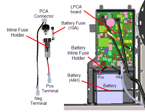
Battery Fuse
The battery inline fuse holder is part of the battery assembly cable attached to the battery positive terminal. To remove the fuse, twist the fuse holder top cap and remove.
Fuse Type: Inline 10 Amp slow blow fuse, .25" diameter
Replacement Procedure
Removal Instructions
Review entire procedure before starting.
- Remove the left Drive Disk cove, see Drive Disk Covers Replacement.
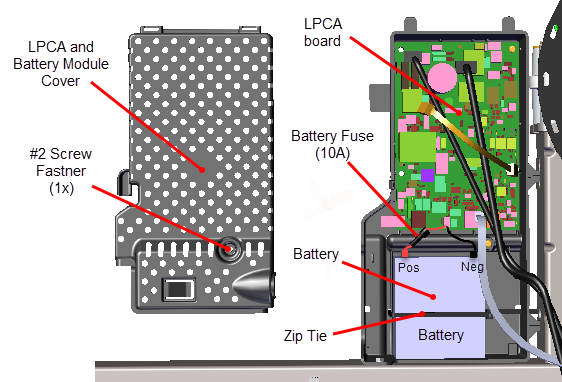
- Remove the one #2 Phillips screw fastener and LPCALower printed circuit assembly; generally this refers to the lower board. On treadmills, this is the motor controller unit (MCU), and on self-powered units, it is the main board in the lower section./Battery Module cover. Retain part(s) and/or fastener(s) for installation.
- Disconnect the negative battery cable (black terminal) and then the positive battery cable (red terminal).
- If installed, cut the zip tie.
- Remove the battery.
Installation Instructions
- Reconnect the positive cable to the positive terminal (red) and then the negative battery cable to the negative terminal (black).
- Reinstall the battery and secure with a cable zip tie.
- Connect the positive cable to the battery red terminal. Make sure the positive cable remains securely connected thru the inline fuse to the LPCA board.
- Connect the negative cable to the battery black terminal. Make sure the negative wire remains securely connected to the frame weldment.
- Reinstall the LPCA/Battery module cover using the one #2 Phillips screw.
- Reinstall the left Drive Disk cove, see Drive Disk Covers Replacement.
- Verify machine operation and return to service, see Operation Verification.