Covers and Panels Replacement
About
These procedures provide instructions to remove and install the EFXElliptical Fitness CrossTrainer covers and panels.
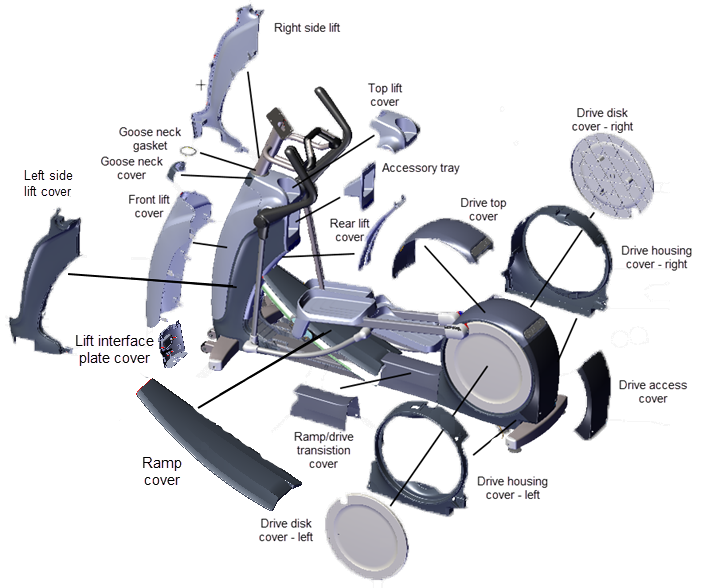
| Cover | Remove/lnstall Procedure |
|---|---|
| Goose Neck Cover | Front Lift Cover Replacement |
| Top Lift Cover | Front Lift Cover Replacement |
| Front Lift Cover | Front Lift Cover Replacement |
| Lift Interface Plate Cover | Lift Interface Plate Cover Replacement |
| Accessory Tray | Accessory Tray Cover Replacement |
| lift Interface Plate | Lift Interface Plate Cover Replacement |
| Ramp Cover | Ramp Cover Replacement |
| Ramp-to-Drive Transition Cover | Drive Housing Covers Replacement |
| Drive Access Panel | Drive Access Panel Replacement |
| Drive Disk Covers | Drive Disk Covers Replacement |
| Drive Top Covers | Drive Housing Covers Replacement |
| Drive Housing Covers | Drive Housing Covers Replacement |
- Removing the front lift cover
 requires first removing the goose neck gasket
  and cover
  , and the top lift cover
  .
.
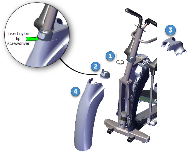
| ID | Description |
|---|---|
|
|
Goose Neck Gasket |
|
|
Goose Neck Cover |
|
|
Top Lift Cover |
|
|
Lift Cover |
Removal Instructions
- Carefully insert the tip of a nylon tipped screwdriver (or similar tool) at the front center of the goose neck in between the goose neck cover and the front lift cover seam. While inserting the nylon tip, apply upward pressure to unsnap the goose neck cover and gasket from the mounting weldment. Remove the goose neck gasket and cover.
Alternative method
You can strike the front of the goose neck cover in an upward motion with the palm of your hand to unsnap the cover from the mounting weldment. Then remove the goose neck gasket and cover.
|
|
CAUTION: Only use nylon tipped screwdrivers (or similar device) to pry and unsnap the goose neck cover. Metal tipped devices will scratch the surfaces and damage the covers. |
- Use your fingers to unsnap and lift the top lift cover
 from the top of the front lift cover
  and accessory tray cover tabs.
 - Use your fingers to unsnap and lift the front lift cover
 from the side cover tabs to remove.
Installation Instructions
- Set the bottom of the front lift cover
 onto the lift interface plate
  and right/left side covers (
 &
&  ) making sure the clips fit over the top edge of the covers. Then press the front cover into onto the right and left side covers making sure the cover tabs lock in place.
 - Position the top lift cover
 into position on top of the accessory tray
  and press to lock tabs in place.
 - Position the goose neck cover
 into position on top of the front lift cover
  and press to lock tabs in place.
 - Reinstall the goose neck gasket
 around the goose neck weldment and press to snap in place. Start at the front and alternately work your way around the weldment tube finishing at the back.
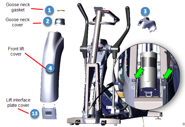
| ID | Description |
|---|---|
|
|
Goose Neck Gasket |
|
|
Goose Neck Cover |
|
|
Top Lift Cover |
|
|
Front Lift Cover |
|
|
Lift Interface Plate Cover |
Removal Instructions
- Remove the goose neck gasket
 , goose neck cover
  , top lift cover
  , and front lift
  cover, see Front Lift Cover Replacement.
 - Remove the two #2 Phillips screw fasteners and remove the lift interface plate cover
 . Retain part(s) and/or fastener(s) for installation.
Installation Instructions
- Reinstall the lift interface plate cover
 , snap the lower tabs in place and align the two fastener bolt holes. Secure with two #3 Phillips screws.
 - Reinstall the lift front cover
 , see Front Lift Cover Replacement.
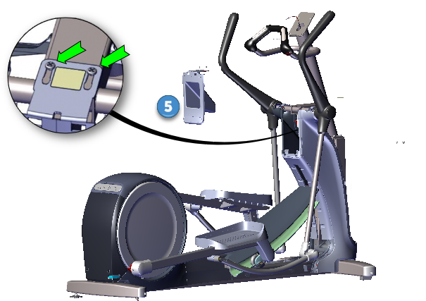
| ID | Description |
|---|---|
|
|
Accessory Tray cover |
Removal Instructions
- Remove the goose neck gasket
 , goose neck cover
  , and lift top cover
  , see Front Lift Cover Replacement.
 - Remove the two #3 Phillips fasteners, Then lift the two top left and right tabs and remove the accessory tray cover
 . Retain part(s) and/or fastener(s) for installation.
Installation Instructions
- Reinstall the accessory tray
 , press to snap the top two left and right tabs in place and secure with the two #3 Phillips screws.
 - Reinstall the goose neck gasket
 , goose neck cover
  , and lift top cover
  , see Front Lift Cover Replacement.
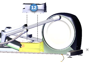
| ID | Description |
|---|---|
|
|
Drive Access Panel |
Removal Instructions
Installation Instructions
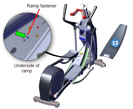
Removal Instructions
- Access the service menu diagnostic CrossRamp Test and set the incline level to 1 (default level)
- P10, P30, P30i and P31: (Service menu (51765761) > MACHINE TEST > CROSSRAMP TEST and raise the INCLINE LEVEL to 1).
- P62, P80, and P82: (Service menu (51765761) > System Settings > System Tests > CrossRamp Test and raise the INCLINE level to 1).
- Disconnect either the battery negative terminal or the Lift Motor input power/control cable.
|
|
WARNING: Make sure to disconnect either the negative battery terminal or the Lift Motor input power/control cable to prevent accidental ramp movement. This unexpected action could cause personal injury. |
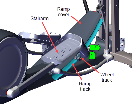
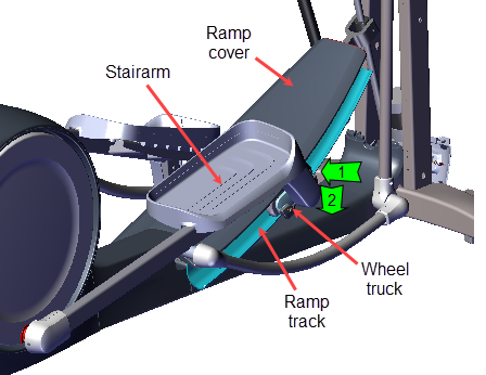
- Remove the Stairarm wheel truck assemble from the ramp track and lay the Stairarm on the floor. To remove, grasp the bottom of the wheel truck assembly and lift up and outward to remove from the track. No tools or fastener removal is required. It may help to lift the outer edge of the CrossRamp cover while removing.
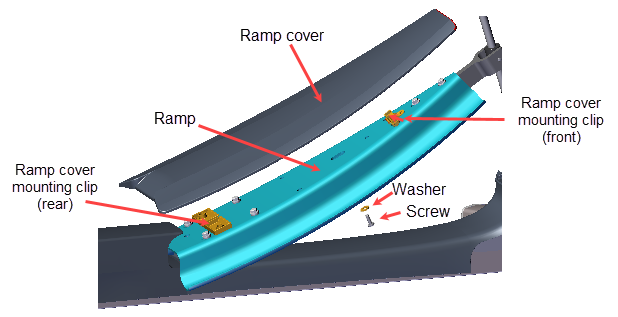
- Use a short stub #3 screwdriver to remove the one screw and washer located on the underside front of the ramp platform. Lift the front of the ramp cover
 and slide forward to remove from retaining clips. Retain part(s) and/or fastener(s) for installation.
Installation Instructions
- Use an approved cleaner (see Cleaning Procedure) to clean the left and right Stairarm wheels and ramp tracks. Dry with a clean cloth. Clean any hard-to-remove grime using a Scotch-Bright pad (or fine steel wool). Dry ramp track surfaces with a clean rag.
- Reinstall ramp cover
 by inserting the rear tabs into the rear ramp platform mounting clips and then pressing down (and/or using the palm of your hand to lightly strike the top of the ramp) on the top front of the ramp to snap into the front bracket clip. Verify that the ramp clips are correctly engaged by grabbing the ramp sides and gently attempting to move and lift the ramp off the platform.
 - Secure ramp
 by reinstalling the #3 Phillips screw fastener and fully tighten.
 - Reinstall the left and right Stairarm wheel trucks onto the Ramp tracks. To install, slip the top of the wheels underneath the CrossRamp cover while lifting the bottom of the wheels over and into the CrossRamp track. You may need to slightly lift up the edge of the CrossRamp cover while inserting the wheels into the CrossRamp track.
- Reconnect either the disconnected battery negative terminal or the Lift Motor input power/control cable.
-
Select QUICKSTART and operate the elliptical at INCLINE level 1 and RESISTANCE level 1 at 130 strides per minute for two minutes, or longer, while listening for wheel/track squeaking or other unusual noises.
- If there are wheel/ramp squeaking noises, apply a thin coat of Swix UR10 Yellow Bio Racing ski wax (or equivalent) to the wheel contact area of the ramp tracks. Rub the wax back and forth across the track several times. .
- Repeat the prior QUICKSTART workout conditions to break-in the new wax application and verify operation.
- At the completion of the wax break-in, gently wipe away any excess wax with a clean rag.
-
Verify operation and return to service, see Operation Verification.

| ID | Description |
|---|---|
|
|
Drive Access Panel |
|
|
Drive Top Cover |
Removal Instructions
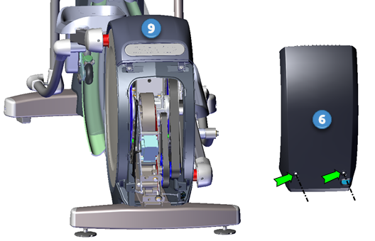
- Use a #3 Phillips screwdriver to remove the two fasteners located at the bottom of the Drive Access panel
 . Slide the access panel downward and away from the drive top cover to remove. Retain part(s) and/or fastener(s) for installation.
Installation Instructions
- Slide the top of the Drive Access panel
 under the lip of the drive top cover
  and then press the cover into position over the access cover opening.
 - Secure cover with the two # 3 Phillips screw fasteners.
| ID | Description |
|---|---|
|
|
Drive Disk Cover - right |
|
|
Drive Disk Cover - left |
Removal Instructions
Repeat this procedure for both the right ![]() and left
and left ![]() Drive Disk coves.
Drive Disk coves.
- Remove the Drive Access panel, see Drive Access Panel Replacement.
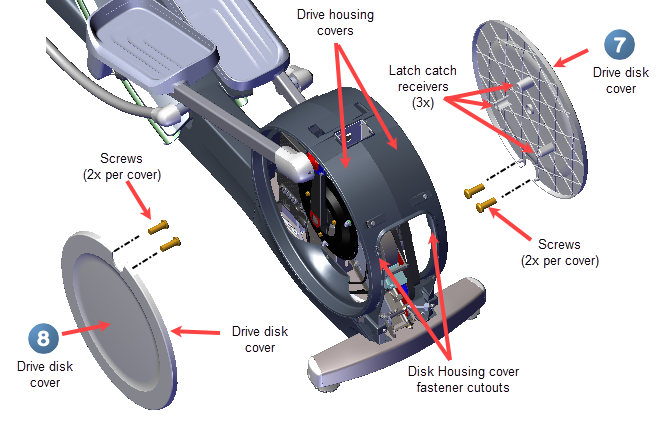
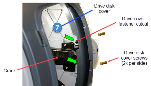
- Rotate the crank until the upper Drive Disk cover attachment screws can be seen through the drive cover fastener cutout. Then use a #2 Phillips screwdriver to remove the screw. Then slowly move the Input Crank upward until the second screw can be seen and remove if installed (there may only be one Drive Disk cover attachment screw installed. However, two screws are required for installation, order any missing screws.). Retain part(s) and/or fastener(s) for installation.
|
|
Note: Some early production units were shipped with only one disk cover crank attachment screw. When reinstalling the disk cover, order two additional screws and use two crank attachment crews per disk cover, see Exploded View Diagrams, bubble # 155. |
|
|
IMPORTANT: Take your time when removing the drive disk mounting screws. The access area is small and it is very easy to accidentally drop the screws down into the drive housing area. If this happens, the drive covers will need to be removed to retrieve the screw. |
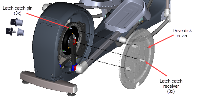
- Use your hand to lightly strike the inside of the drive disk to unsnap the disk from the three latch catch pins and remove. Rotate the drive disk to position one of the three latch catch pins at the rear of the housing and then use your hand to strike the inside of the drive disk to unsnap the disk from the latch catch pin, Repeat for the two remaining latch catch pins and remove the cover.
Installation Instructions
Repeat this procedure for both the right and left Drive Disk coves.
- Position the Drive Disk cove over the crank aligning the three latch catch receivers over the latch catch pins. Then lightly strike the Drive Disk cove at each latch catch pin location to snap in place. Make sure all three latch catch pins are secure.
- Rotate the crank until one of the two Drive Disk cove attachment screw holes can be seen through the drive cover fastener cutout. Then install the #2 Phillips screw and fully tighten. Move the crank to the second attachment screw hole and install the second screw. If the second screw is missing, order a new screw and install (two fastener screws (two per side are required), see Exploded View Diagrams, bubble #155.

|
|
Note: Some early production units were shipped with only one disk cover attachment screw. Two cover crank fasteners are now required. If missing screws, order additional screw, see Exploded View Diagrams, bubble #155. |
- Reinstall the Drive Access panel, see Drive Access Panel Replacement.

| ID | Description |
|---|---|
|
|
Drive Top Cover |
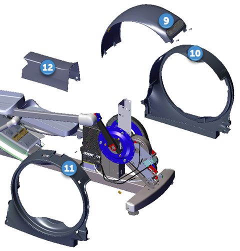
|
|
Drive Housing Cover - Right |

|
Drive Housing Cover - Left |
|
|
Ramp-to-Drive Transition Cover |
Removal Instructions
Repeat this procedure for both the right and left drive housing covers.
- Remove the Drive Access panel, see Drive Access Panel Replacement.
- Remove the left and right Drive Disk coves, see Drive Disk Covers Replacement.
- Remove the left and right Stairarms off the Input Drive Cranks, see Stairarm Replacement.
- Remove the ramp-to-drive transition cover
 by pulling the bottom edges slightly apart and lifting upward to remove.
 - Remove the drive top cover:
- Remove the two top cover
 #3 Phillips screw fasteners. Retain part(s) and/or fastener(s) for installation.
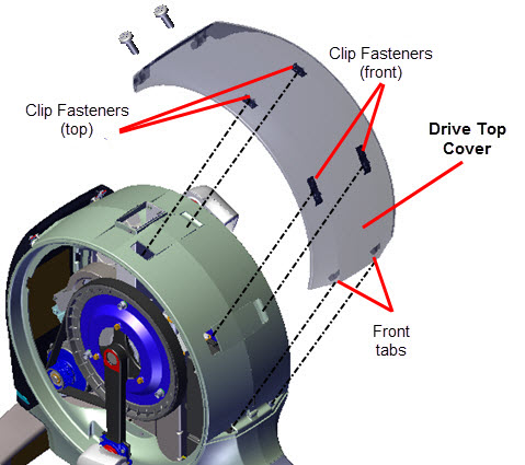
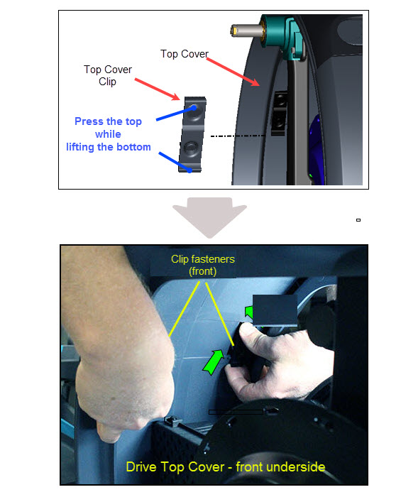
 - Straddle the rear housing and reach into the underside of the top cover to unsnap the left and right front clip fasteners. Simultaneously use your thumbs to press down on the top of the clips while using your forefingers to grab and lift upward on the bottom of the clips to release. Continue to slide the top cover forward and lift up to remove.
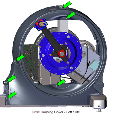
- Use a 5/16" socket to remove the six screw fasteners from the left drive housing cover
 . Carefully slide the cover over the crank and remove. Retain part(s) and/or fastener(s) for installation.
|
|
Note: The left drive housing cover must be removed prior to removing the right cover. |
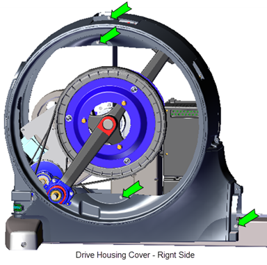
- Use a 5/16" socket to remove the four screw fasteners from the right drive housing cover
 . Unplug the ASLActive Status Light: Service and maintenance status light. light input cable. Carefully slide the cover over the crank and remove. Retain part(s) and/or fastener(s) for installation.
Installation Instructions
- Carefully slide the right drive housing cover
 over the crank. Reconnect the ASL light input cable. Place the cover into position and use a 5/16" socket to reinstall the four screw fasteners.
 - Carefully slide the left drive housing cover
 over the crank. Place the cover into position and use a 5/16" socket to reinstall the five screw fasteners.
 - Reinstall the drive top cover
 . Position the top cover onto the housing and while applying light pressure first insert the top housing clips and then simultaneously inserting the top cover front tabs into the front housing mounts and inserting the front clips into the front housing brackets. Make sure the top cover clips are secure and install the two #3 Phillips screw fasteners.
 - Reinstall the ramp-to-drive transition cover
 . Press on cover to securely lock tabs in place, see Covers and Panels Replacement.
 - Reinstall the left and right Stairarms onto the Input Drive Cranks, see Stairarm Replacement.


- Reinstall the left and right Drive Disk coves, see Drive Disk Covers Replacement.
- Reinstall the Drive Access panel, see Drive Access Panel Replacement.
- Verify the machine operation and return to service.