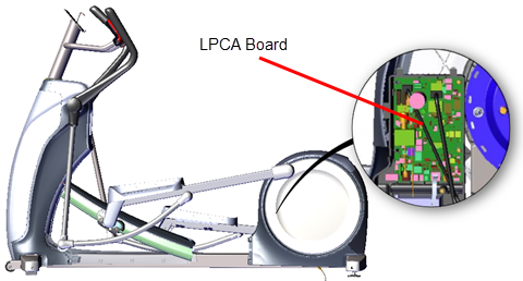
LPCA (Lower PCA) Board Replacement
About
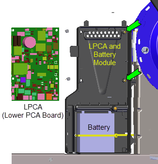
This procedure provides instruction to remove and install the LPCALower printed circuit assembly; generally this refers to the lower board. On treadmills, this is the motor controller unit (MCU), and on self-powered units, it is the main board in the lower section. (Lower PCALower printed circuit assembly; generally this refers to the lower board. On treadmills, this is the motor controller unit (MCU), and on self-powered units, it is the main board in the lower section.) board.
LPCA System Block Diagram
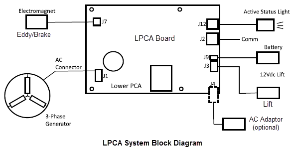
LPCA Interface Connections
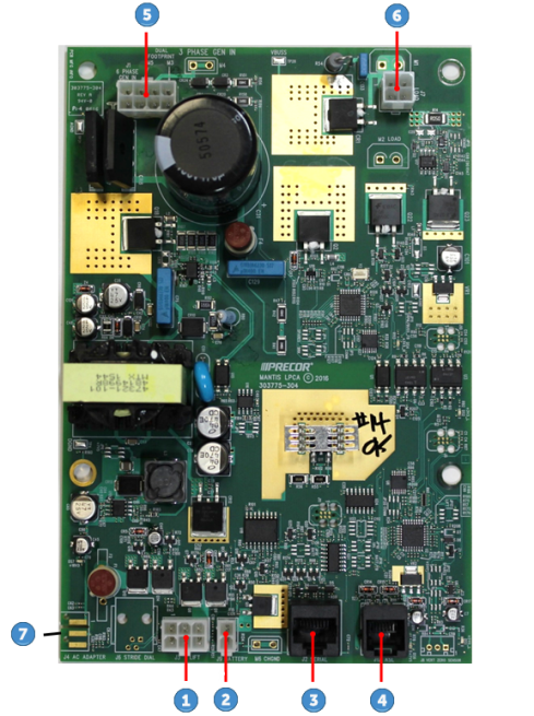
| ID | Interface |
|---|---|
| Lift (J3) | |
| Battery (J9) | |
| Comm Serial (J2) | |
| Active Status Light (J12) | |
| Generator (J1) | |
| Eddy/Brake (J7) | |
| ACAlternating Current: electric current which periodically reverses direction between positive and negative polarity. Adapter (J4) |
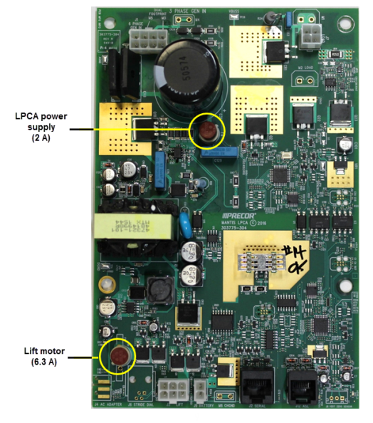
LPCA Fuse Locations
There are two replaceable fuses located on the LPCA board:
- 2 Amp LPCA power supply
- 6.3 Amp lift motor fuse.
Procedure
Review entire procedure before starting.
Removal Instructions
- Remove the Left Drive Disk Cover, see Drive Disk Covers Replacement.
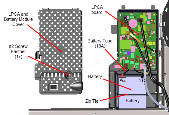
- Remove the one #2 Phillips screw fastener and remove the LPCA/Battery Module cover. Retain part(s) and/or fastener(s) for installation.
- Disconnect the Positive (Red) and Negative (Black) battery terminal cables.
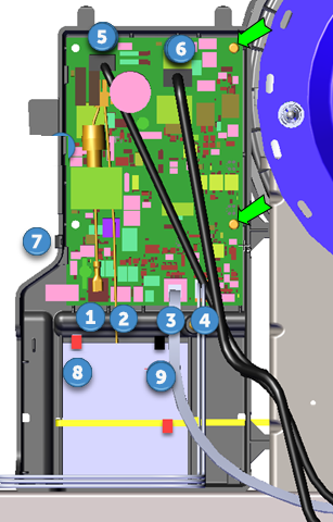
- Remove the following LPCA interface cables:
- Disconnect the Generator (J1) cable
 .
. - Disconnect the Eddy/Brake (J7) cable
 .
. - Disconnect the Lift (J3) cable
 .
. - Disconnect the Battery (J9) cable
 .
. - Disconnect the Comm Serial (J2) cable
 .
. - Disconnect the Active Status Light (J12) cable
 .
. - Remove the two #2 Phillips screw fastener and remove the LPCA board. Retain part(s) and/or fastener(s) for installation.
- If attached, disconnect the AC Adapter (J4) cable
 .
.
Installation Instructions
- If removed, reinstall the AC Adapter (J4) cable .
- Reinstall the LPCA board using the two #2 Phillips screw fasteners.
- Reconnect the following LPCA interface cables:
- Reconnect the Lift (J3) cable .
- Reconnect the Battery (J9) cable .
- Reconnect the Comm Serial (J2) cable .
- Reconnect the Active Status Light (J12) cable .
- Reconnect the Generator (J1) cable .
- Reconnect the Eddy/Brake (J7) cable .
- Reconnect the Positive (Red) and Negative (Black) battery terminal cables.
- Reinstall the LPCA/Battery module cover using the one #2 Phillips screw fastener.
- Reinstall the Left Drive Disk cover, see Drive Disk Covers Replacement.
- Verify machine operation and return to service, see Operation Verification.