Generator Assembly Replacement
Applies To: (Spinner® ChronoSpinner® Chrono™ Power bike.™ Power models only)
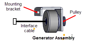
About
This procedure provides instruction to remove and install the Generator Assembly.
Specifications
| System Component | Specification |
|---|---|
| Generator Belt Tension | 1/2 in (1.3 cm) up/dwn travel |
|
Generator Output |
Voltage: approx. 9 Vac @ 60 rpm |
Procedure
Review entire procedure before starting.
- Remove the front and rear drive belt covers, see Belt Guard Cover Replacement.
- Remove all brake resistance by turning the resistance knob counter clockwise (-).
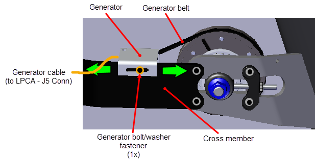
- Disconnect the generator interface cable from the LPCALower printed circuit assembly; generally this refers to the lower board. On treadmills, this is the motor controller unit (MCU), and on self-powered units, it is the main board in the lower section. - 5 connector. Cut the two cable ties that hold the cable to the cross member and remove.
- Loosen the generator 4 mm hex key mounting bolt enough so that the generator can be moved forward. Move the generator forward to loosen tension and remove the belt off the generator pulley.
- Remove the 4 mm hex key bolt and washer mounting fasteners and remove the generator.
Removal procedure
Installation procedure
- Install the generator onto the cross member and secure using the 4 mm hex key bolt and washer fasteners. Loosely tighten the fasteners allowing forward and rearward movement.
- Install the generator belt onto the generator and flywheel generator pulleys.
- Route the generator interface cable across the cross member and connect to the LPCA - J5 connector. Reinstall the previously removed two cable ties that hold the generator and other electrical component interface cables to the cross member.
- Adjust the generator belt tension see Generator Belt Tension Adjustment.
|
|
CAUTION: Do not over tension the belt which will lead to premature belt wear and possible damage to the generator pulley. |
- Access the console service test menu and select RPM. Pedal the bike and verify that the RPMs value is showing and varies with pedal speed.
|
|
Note: RPM is computed from pin 3 of the generator cable connector. If this generator output phase has quite working, the console may not operate and will not display RPM. |
- Ride and pedal the bike at 60 rpms and verify that the generator is providing the specified charging voltage and current. Access the console service test menu and verify the generator voltage and current outputs:
- GEN VOLT: approx. 9 Vac @ 60 rpm (voltage will increase as rpms increase)
- GEN AMP: approx. 0.4 amps @ 60 rpm (current will increase as rpms increase)
- Reinstall the front and rear drive belt covers, see Belt Guard Cover Replacement.
- Verify the bike operation per Operation Verification Checklist and return to service.
.See Also