Resistance Knob Replacement
About
This procedure provides instruction to remove and install the Resistance Knob assembly.
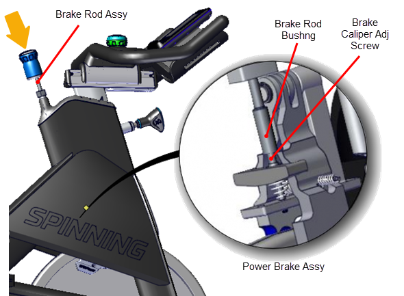
The resistance knob is part of the Brake Rod Assy. Replace the Brake Rod Assy to replace the Resistance Knob
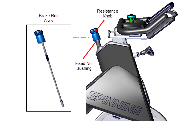
Procedure
Review entire procedure before starting.
Removal Instructions
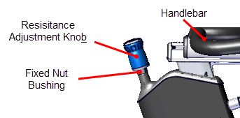
- Expose the Fixed Nut Bushing by turning the Resistance Knob counterclockwise (-) until the stop is reached.
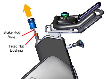
- Use a 21 mm open end wrench to loosen the Fixed Nut Bushing while lifting the Brake Rod Assy and Resistance Knob from the bike frame.
|
|
Note: The bushing at the end of the brake rod may catch on the caliper preventing the rod from being lifted out of the frame weldment. If this occurs, the caliper will need to be removed to extract the brake rod assembly, Brake Caliper Assembly Replacement. |
Installation Instructions
- If the brake caliper was removed to extract the brake rod assembly, reinstall the caliper, see Brake Caliper Assembly Replacement.
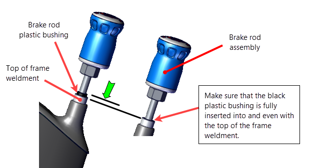
- Before installing the brake rod assembly, make sure that the brake rod plastic bushing is fully inserted into the frame weldment.
- Carefully reinstall the Brake Rod Assy in the bike frame. Make sure the bushing at the end of the Brake Rod fits over the Power Brake Assy - Caliper Adjustment Screw.
- Tighten the Brake Rod Assy - Fixed Nut Bushing.
- Set the resistance to minimum.
- Start pedaling the bike greater than 55 rpm while increasing the resistance level to maximum and returning to minimum resistance.
- Verify smooth resistance operation from minimum to maximum levels.
- Verify that at maximum resistance, the pedal resistance was very strong.
- Verify that there were no unusual noises from the brake pads during this operation.
- While riding the bike, stop pedaling and firmly press down the resistance knob. Verify that the flywheel immediately slows down and stops rotating.
- Verify the bike operation per Operation Verification Checklist and return to service.

See Also