Lift Motor Calibration
About
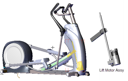
This procedure provides instruction to verify and calibrate the Lift Motor and Incline system. The Lift Motor calibration should be verified anytime the Lift Motor fuse fails or is replaced or any incline system component is replaced.

Specifications
| System Component | Specification |
|---|---|
| Lift Motor Calibration Distance* | 9" +/- 1/4" (23 cm +/- 0.6 cm |
| Yoke/Ramp Fasteners | 330 in-lbs (27.5 ft-lbs or 37.2 Nm) |
| Note: * Calibration distance is set at incline level 10. | |
Procedure
Review entire procedure before starting.
|
|
TIP: To help keep your hands clean while doing this procedure, it is advised to wear general purpose mechanics gloves. You will be handling the jackscrew which is coated with a thin layer of grease. |
Lift Motor Calibration Verification
- Remove the Front Lift cover, Lift Interface Plate cover, and Ramp cover, see Front Lift Cover Replacement, Lift Interface Plate Cover Replacement, and Ramp Cover Replacement procedures.
- .Access the CROSSRAMP TEST diagnostic test and raise the crossramp incline to level 10.
- .On LED (P10, P30, P30i and P31) consoles: Access diagnostic test menu (51765761) and select MACHINE TEST > CROSSRAMP TEST.
- .On Touchscreen (P62, P80, and P82) consoles: Access the Service menu (51765761) and select System Settings > Systems Test > CrossRamp Test.
- Then disconnect the Lift Motor input power cable to prevent accidental ramp incline movement.
|
|
WARNING: Make sure to disconnect the Lift Motor input power/control cable or it is possible for the crossramp to automatically lower to level 1 if either the pedals or arms are moved. This unexpected action could cause personal injury. |
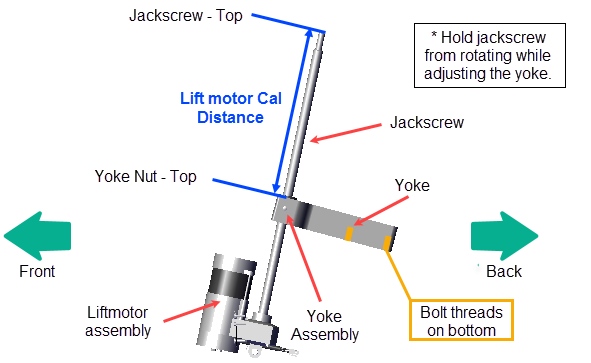
- Measure and verify that the distance from the top of the jackscrew to the top of the yoke nut is 9" +/- 1/4" (23 cm +/- 0.6 cm.
- If the calibration distance is not to specification (lift motor calibration distance: 9" +/- 1/4" (23 cm +/- 0.6 cm), continue procedure to adjust the Lift Motor calibration distance
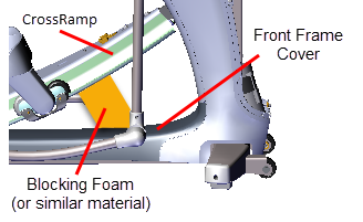
- Place a pad over the top of the Front Frame cover to protect the surface during the adjustment procedure. Place blocking material (hard foam or similar material) between the underside of the ramp and frame to support and keep the ramp in the raised position.
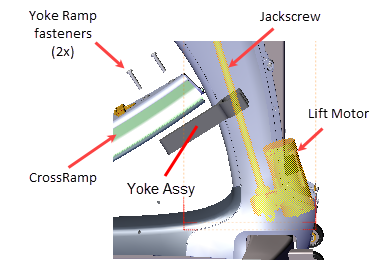
- Use a 9/16" socket to remove the two yoke ramp fasteners and remove the yoke from the ramp. Note that the ramp will fall when the fasteners are removed. Make sure the ramp is supported before removing the yoke ramp fasteners. Retain part(s) and/or fastener(s) for installation.
- Tilt the jackscrew forward out of the front tower weldment. Then use one hand hold the jackscrew fixed and the other hand to rotate the yoke nut around the jackscrew to raise or lower as needed to adjust the calibration distance to 9" +/- 1/4" (23 cm +/- 0.6 cm.

Lift Motor Calibration


|
|
IMPORTANT: It is important to keep the jackscrew fixed (not allowed to rotate) as the yoke nut is being adjusted. If the jackscrew does rotate during the adjustment, the lift motor will need to be reset to level 10 and then the yoke nut recalibrated. |

- Reattach the Yoke to the Ramp using the two yoke ramp fasteners, torque to 330 in-lbs (27.5 ft-lbs or 37.2 Nm).
- Remove any blocking materials and pad.
- Reconnect the lift motor input power cable.
- .Verify the crossramp incline operation through the full range of motion, levels 1 thru 20. Access the CROSSRAMP TEST diagnostic test and then lower and raise the crossramp incline several times from the minimum to maximum levels.
- .On LED (P10, P30, P30i and P31) consoles: Access diagnostic test menu (51765761) and select MACHINE TEST > CROSSRAMP TEST.
- .On Touchscreen (P62, P80, and P82) consoles: Access the Service menu (51765761) and select System Settings > Systems Test > CrossRamp Test.
- Reinstall the Front Lift, Lift Interface Plate, and Ramp covers, see Front Lift Cover Replacement, Lift Interface Plate Cover Replacement and Ramp Cover Replacement procedures.
- Verify elliptical operation and return to service, see Operation Verification.