Linkarm Replacement
About
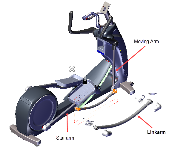
This procedure provides instruction to remove and install the Moving Arms.
Specifications
| System Component | Specification |
|---|---|
| Moving Arm/Link Arm Bolt | 300 +/- 90 in-lbs (34 +/- 10 Nm) |
Procedure
Review entire procedure before starting.
Removal Instructions
Repeat this procedure for both the right and left Moving Arm removal.
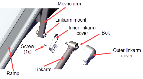
- Disconcert the Linkarm from the Moving Arm:
- Remove the #2 Phillips screw and the Outer Linkarm cover. Retain part(s) and/or fastener(s) for installation.
- Loosen the 9/16" Linkarm hex bolt and remove the Linkarm from the Moving Arm. Retain part(s) and/or fastener(s) for installation.
- Remove the Inner Linkarm cover from the Moving Arm. Retain part(s) and/or fastener(s) for installation.
- Remove the Linkarm from the Moving Stairarm:
- Remove the #2 Phillips screw fastener and remove the Outer Linkarm Cover. Retain part(s) and/or fastener(s) for installation.
- Remove the 9/16" hex head screw and remove the Linkarm from the Stairarm weldment - Linkarm bracket and carefully lay onto the floor.
- Remove the Inner Linkarm cover, and Linkarm Transition cover from the Stairarm weldment - Linkarm bracket. Retain hardware and fastener for installation.
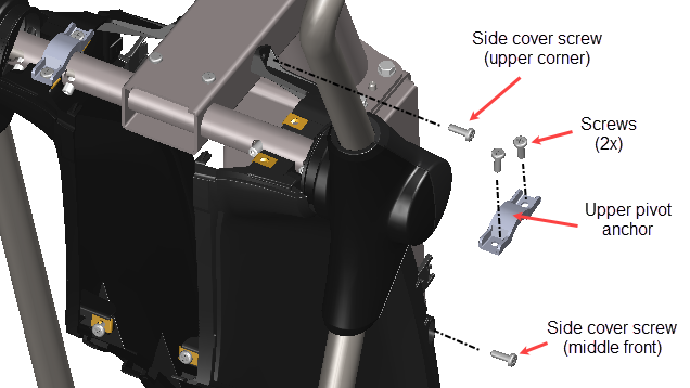
- Loosen the top half of the side cover from the front tower weldment:
- Remove the front upper corner and the middle front #3 Phillips side cover weldment screws.
- Then remove the two #2 Phillips screws and the Upper Pivot Anchor bracket.
- Remove the Moving Arm:
- Loosen, but do not remove, the 3/16" hex key pivot shaft outer set screw.
- Then remove the 3/16" hex key pivot shaft inner set screw and gently pull the Moving Arm outward and over the side cover to remove. Retain part(s) and/or fastener(s) for installation.

Installation Instructions
- Reinstall the Moving Arm pivot shaft into the weldment moving arm pivot mount bar.
- Then reinstall the 3/16" hex key pivot shaft inner set screw.
- If the 3/16" hex key pivot shaft outer set screw was removed, reinstall the outer set screw.
- Tighten both the inner and outer set screws and torque to 300 in-lbs (34 Nm).
- Reinstall the upper corner and middle front #3 Phillips side cover weldment screws, torque to 30 +/- 9 in-lbs (3.4 +/- 1 Nm).
- Reinstall the Upper Pivot Anchor bracket and secure using the two #2 Phillips screws, torque to 30 +/- 9 in-lbs (3.4 +/- 1 Nm).
- Reattach the Linkarm to the Moving Arm:
- Reinstall the Inner Linkarm cover onto the Moving Arm - Linkarm mount.
- Then attach the Linkarm to the Moving Arm and secure using the 9/16" bolt, torque to 300 +/- 90 in-lbs (34 +/- 10 Nm).
- Reinstall the Outer Linkarm cover and secure using the #2 Phillips screw.
- Reinstall the Lift Rear cover (see Covers and Panels Replacement), Accessory Tray (see Accessory Tray Cover Replacement), and Lift Front Cover (see Front Lift Cover Replacement).
- Verify machine operation and return to service, see Standard Service Menus.