LPCA board Replacement
Applies To: (Spinner® ChronoSpinner® Chrono™ Power bike.™ Power models only)
About
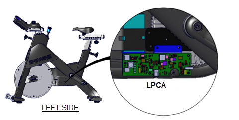
This procedure provides instruction to remove and install the LPCALower printed circuit assembly; generally this refers to the lower board. On treadmills, this is the motor controller unit (MCU), and on self-powered units, it is the main board in the lower section. (Lower PCALower printed circuit assembly; generally this refers to the lower board. On treadmills, this is the motor controller unit (MCU), and on self-powered units, it is the main board in the lower section.) board.
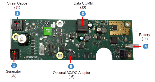
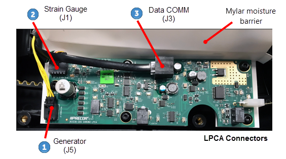
LPCA Interface Cable Connections
| ID | Interface Cables |
|---|---|
|
|
Generator (J5) |
|
|
Strain Gauge(J1) |
|
|
Data COMM(J3) |
|
|
Battery (J4) |
|
|
Optional ACAlternating Current: electric current which periodically reverses direction between positive and negative polarity./DCDirect Current: electrical current that only flows in one direction. Power Adapter(J1) |
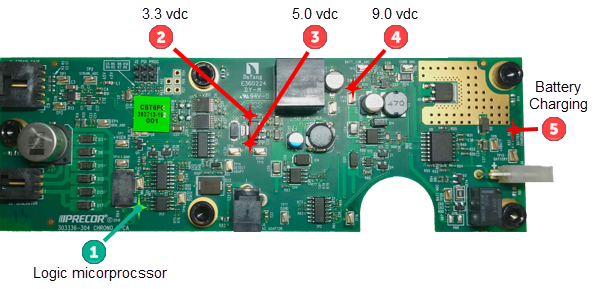
LPCA Status LEDs
| ID | LED Description |
|---|---|
|
|
Logic microprocessor ON (flashes green) |
|
|
3.3 Vdc supply (red) |
|
|
5 Vdc supply (red) |
|
|
9 Vdc supply (red) (while pedaling or AC/DC adapter plugging in) |
|
|
Battery Charging (red)
|
Procedure
Review entire procedure before starting.
|
|
CAUTION: Electronic components can easily be damaged by electrostatic discharge (ESD). Always use properly grounded anti-static wrist-strap and anti-static mat when handling or servicing printed circuit boards. |
Removal Instructions
- Remove the front and rear belt guard covers, see Belt Guard Cover Replacement.
- Disconnect the battery cable Black wire from the Negative (-) battery terminal and then the Red wire from the Positive (+) battery terminal, see Battery Replacement . Disconnect the battery Negative (-) terminal wire first:
- Disconnect the battery cable
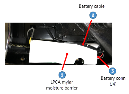
 from the LPCA battery connector (J4)
  , see the following diagram. (If there is a LPCA moisture barrier
  cable tie
  installed, cut, remove, and discard.)
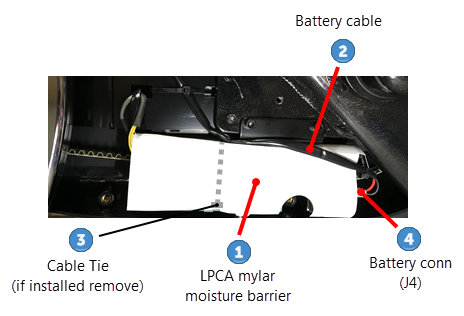
- If installed, cut the cable tie that secures the Mylar moisture barrier to the front of the LPCA board.
- Lift the Mylar moisture barrier and disconnect the Generator (J5)
 cable connector, then the Data COMM (J3)
  cable connector and last the Strain Gauge (J1)
  cable connector.
|
|
CAUTION: Do not cut the Mylar moisture barrier to either remove or install the strain gauge cable connector. Cutting the barrier will allow sweat and other fluids to damage the LPCA board. |
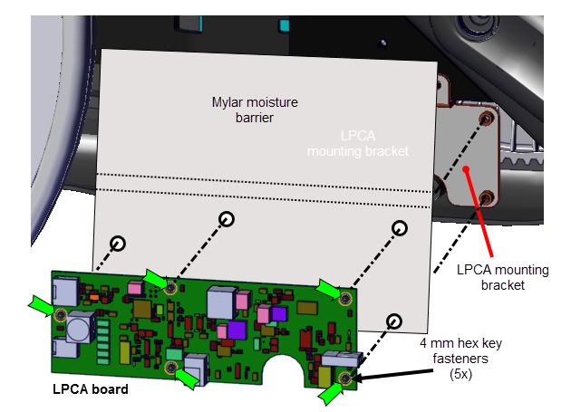
- Remove the five 4 mm hex key bolts (5x) and remove the LPCA board and Mylar moisture barrier. Retain the Mylar moisture barrier and fasteners for installation.
Installation Instructions
- Position the Mylar moisture barrier and LPCA board onto the LPCA mounting bracket. Reinstall the five 4 mm hex key bolts and fully tighten.
- Reconnect the Strain Gauge (J1) cable connector, then the Data COMM (J3) cable connector and last the Generator (J5) ,cable connector. Do not cut the Mylar moisture barrier to connect the Strain Gauge (J1) cable connector.
|
|
CAUTION: Do not cut the Mylar moisture barrier to either remove or install the strain gauge cable connector. Cutting the barrier will allow sweat and other liquids to damage the LPCA board. |
- Fold the Mylar moisture barrier over the front of the LPCA board and then route the battery cable over the moisture barrier and reconnect to the LPCA battery cable connector (J4) , see the following diagram.
|
|
Note: Do not install a zip tie to hold the moisture barrier cover over the LPCA board. |
- Reconnect the battery cable Red wire to the Positive (+) battery terminal and then the Black wire to the Negative (-) battery terminal, see Battery Replacement. Reconnect the Negative terminal cable last:
- Reinstall the front and rear belt guard covers, see Belt Guard Cover Replacement.
- Verify machine operation and return to service, see Operation Verification.
.See Also