Lift Motor Calibration
About
This procedure provides instruction to verify and calibrate the Lift Motor and Incline system. The Lift Motor calibration should be verified any time the lift motor is replaced, the lift motor fuse fails, or any incline system component is replaced.
Specifications
| System Component | Specification |
|---|---|
| Lift Motor Calibration Distance* | 1 1/8 in - 1 3/16 in (2.8 cm - 3.0 cm) |
| Note: * Calibration distance is specified at incline level 0. | |
Procedure
Review entire procedure before starting.
- Remove the Hood cover, see Hood Cover Replacement.
-
Choose either the side or front access method to position the treadmill to access the lift motor jackscrew. Go to the following selected side or front access procedures and return to continue the calibration.
- Side lift motor access method, go to Side lift platform assembly access,
- Front lift motor access method, go to Front lift platform assembly access.
|
|
WARNING: Keep hands and appendages clear of the incline platform assembly before switching power ON. Switching power ON will cause the incline platform to move to the level "0" Home position. |
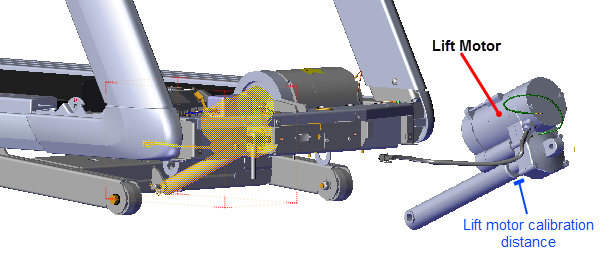
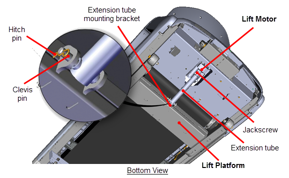
- Measure the lift motor calibration distance between the top of the extension tube nut and the bottom of the lift motor actuator jackscrew housing. Verify that the distance is within the specified limits specification limit 1 1/8 in - 1 3/16 in (2.8 cm - 3.0 cm) (incline level set to "0"):
- If the distance is within the specified limit, calibration is not required. Go to Operation Verification, see Operation Verification.
- If the distance is NOT within the specified limit, continue procedure and calibrate the lift motor assembly.
- Disconnect the extension tube from the lift platform weldment mounting bracket by removing the hitch pin and clevis pin. Retain part(s) and/or fastener(s) for installation.
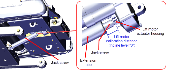
- Firmly hold the jackscrew and rotate the extension tube to adjust the calibration distance. The calibration distance is measured between the top of the extension tube nut and the bottom of the lift motor actuator housing. Make sure the calibration distance is within the specification limit 1 1/8 in - 1 3/16 in (2.8 cm - 3.0 cm).
- Reinstall the extension tube into the lift platform mounting bracket and secure using the hitch pin and clevis pin. It may be necessary to slightly rotate the extension tube to align the clevis pin mounting holes. Choose an adjustment direction that will minimize the change to the extension tube calibration distance. Firmly hold the jackscrew from turning while adjusting (rotating) the extension tube.
- Return the treadmill to the default upright position making sure the treadmill is stable and setting level on the floor, see either the Side lift platform assembly access or the Front lift platform assembly access.
- Reinstall the hood.
- Connect the power cord and switch the power ON.
- Verify incline operation from the minimum to maximum levels.
- Do the Operation Verification tests (see Operation Verification) and return to service.
Lift motor calibration adjustment
Lift Platform Assembly Access
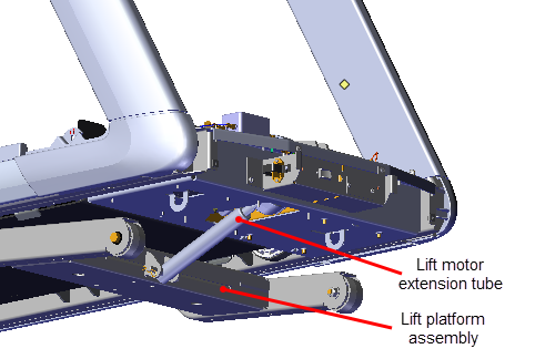
Servicing the lift platform assembly and lift motor extension tube/jackscrew components require accessing the underside of the treadmill. There are two alternative methods to access the lift platform assembly and connected hardware: 1) side lift platform assembly access or 2) front lift platform assembly access. Review each method and use the process that best fits your particular circumstances.
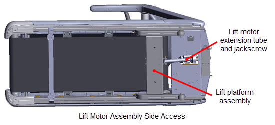
Side lift platform assembly access
This method accesses the lift platform assembly and connected hardware by laying the treadmill on its side.
Laying the treadmill on its side
- Toggle the power switch from OFF to ON. This will reset the incline level to "0" (the incline level "Home" position). Incline level "0" is also the lift motor calibration reference incline level.
|
|
IMPORTANT: It is important to set the incline level to "0" (calibration ref level) before switching the power OFF. |
- Switch the power OFF and unplugDisconnect a device power cord plug or cable connector from the power receptacle or outlet. the power cord. Move the power cord so it will not be damaged as the treadmill is laying on its side.
- If not already removed, remove the Hood cover Hood Cover Replacement.
- Clear the area of any obstructions or items that could damage or be damaged as the treadmill is tipped on its side.
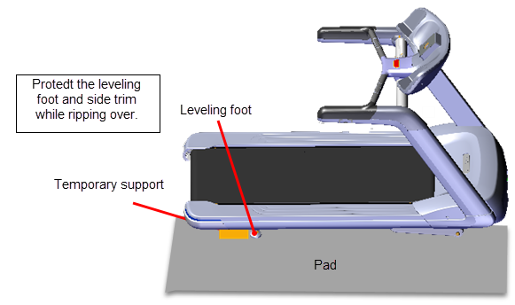
- Tip the treadmill on its side while being careful to not damage or break off the rear leveling foot. You can use soft blocking material next to the leveling foot to support the frame weight as the treadmill is being tipped over.
|
|
CAUTION: Protect the leveling feet from damage while tipping the treadmill on its side. |
Returning the treadmill to the upright position
- Switch the power OFF and unplug the power cord. Move the power cord so it will not be damaged as the treadmill is set to the upright position.
- Clear the area of any obstructions or items that could damage or be damaged as the treadmill is tipped to the upright position.
- Tip the treadmill to the upright position while being careful to not damage or break off the rear leveling foot. You can use soft blocking material next to the leveling foot to support the frame weight as the treadmill is being tipped over.
|
|
CAUTION: Protect the leveling feet from damage while tipping the treadmill to the upright position. |
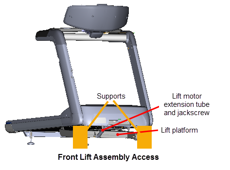
Front lift platform assembly access
This method accesses the lift platform assembly and connected hardware from the front of the treadmill by raising and supporting the treadmill front frame weldment.
Raising and supporting the treadmill
- Connect the power cord and switch the input power ON.
- Access the service menu (51765761) and select INCLINE TEST. Use the incline control to set the incline level to 14.
- Securely and safely place supports (e.g. car jack stands) under the left and right front corners of the frame weldment.
- Slowly lower the incline level in 0.5 increments setting the frame onto the supports. Verify the supports are stable carrying the weight of the treadmill and continue lowering the incline level to "0". Incline level "0" is also the lift motor calibration reference incline level.
|
|
IMPORTANT: It is important to set the incline level to "0" (calibration ref level) before switching the power OFF. |
- Switch the power OFF and unplug the power cord.
Removing supports and lowering the treadmill
- .Connect the power cord and switch the power ON. Be aware that switching the power ON will cause the incline platform to move and return to the level "0" position.
|
|
WARNING: Keep hands and appendages clear of the incline platform assembly before switching power ON. Switching power ON will cause the incline platform to move to the level "0" Home position. |
- Access the service menu (51765761) and select the INCLINE TEST. Increase the incline level enough to lift the treadmill frame off the supports.
- Remove the support stands and clear any other items that might either block the treadmill from lowering or may be damaged as it lowers.
- Lower the incline to level "0".