ASL PCA Replacement
About
This procedure provides instruction to replace the ASLActive Status Light: Service and maintenance status light. PCAPrinted circuit assembly, generally referred to as either an upper PCA or lower PCA. board.
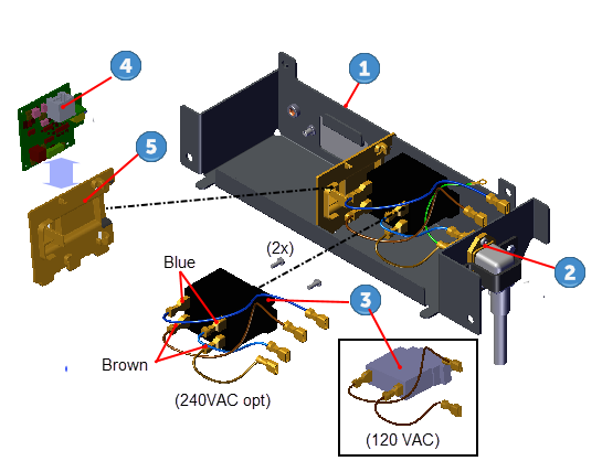
The Power Entry Assembly located in the front of the treadmill under the frame weldment cross member contains the Power Cord Inlet Assembly, the ON/OFF SW Circuit Breaker, and the ASL PCA board. The Power Entry Assembly Bracket must be removed to access these components.

| ID | Description |
|---|---|
|
|
Power Entry Assembly Bracket |
|
|
Power Cord Inlet Assy |
|
|
ON/OFF SW Circuit Breaker |
|
|
ASL PCA Board |
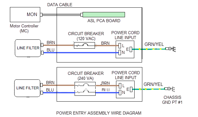
Wire Diagram
Power Entry Assembly wire diagram.
Procedure
Review entire procedure before starting.
| ID | Description |
|---|---|
|
|
Power Entry Assembly Bracket |
|
|
Power Cord Inlet Assembly |
|
|
ON/OFF SW Circuit Breaker |
|
|
ASL PCA |
|
|
ASL PCA Bracket |
Removal Instructions
- Switch the power OFF and unplugDisconnect a device power cord plug or cable connector from the power receptacle or outlet. the power cord.
|
|
TIP: For easier access, raise the incline to maximum before removing power. Access the service Hardware Validation (51765761) and use the CROSSRAMP/INCLINE Test to raise the incline and then remove power. |
- Remove the hood cover, see Hood Cover Replacement.
- Remove the four #3 Phillips fasteners and remove the Power Entry Assembly bracket
 . Hold the bracket while removing to prevent wire cable damage. Retain part(s) and/or fastener(s) for installation.
 - Disconnect the ASL interface cable RJ11 connector, see Wire Diagram.
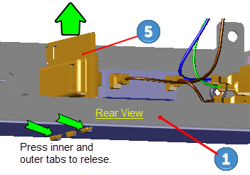
- Remove the ASL PCA Bracket
 by pressing the inner and outer tab clips on the bottom (underside) of the Power Entry Assembly Bracket while lifting the ASL bracket.
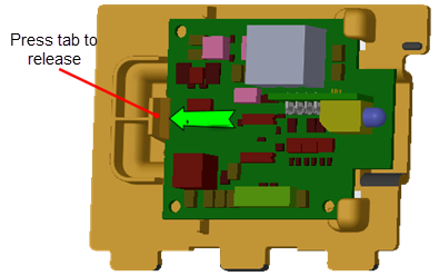
 - Unsnap the ASL PCA
 board from the ASL PCA Bracket by pressing the outer tab clip to remove.
Installation Instructions
- Reinstall the ASL PCA board onto the ASL PCA Bracket . Securely snap the ASL PCA board into position on the bracket.
- Reinstall the ASL PCA Bracket by pressing the tabs into the mounting slots on the Power Entry Assembly Bracket .
- Reconnect the ASL interface cable RJ11 connector, see Wire Diagram.
- Reinstall the Power Entry Assembly bracket and secure using the four #3 Phillips fasteners. Make sure that the wire cables are not pinched or damaged during installation.
- Reinstall the hood cover, see Hood Cover Replacement.
- Connect the power cord and switch the ON/OFF circuit breaker ON.
- Verify the ASL light operation:
- Verify that the ASL light is Solid Blue. If the ALS light is Pulsing Blue, Pulsing Yellow, or Solid Yellow, resolve the issue and reset the ASL to Solid Blue.
- Do the Operation Verification tests (see Operation Verification) and return to service.