Input Drive Assembly Replacement
About
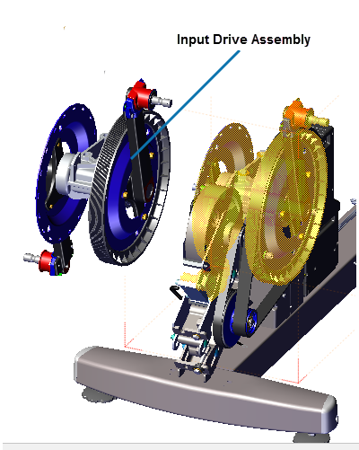
This procedure provides instruction to remove and install the Input Drive Assembly.
Specifications
| System Component | Specification |
|---|---|
| Input Drive Assembly Nylock Bolts | 300 +/- 90 in-lbs (34 +/- 10 Nm) |
Procedure
Review entire procedure before starting.
Removal Instructions
- Remove the Drive Access cover see Drive Access Panel Replacement.
- Remove the left and right drive disk and Drive Top covers, see Drive Disk Covers Replacement.
- Remove the left and right Stairarms from the Input Crank, see Stairarm Replacement
- Remove the Drive Housing covers see Drive Housing Covers Replacement.
- Use a 1/2" socket to loosen the two Drive Components assembly fastener nuts (left side). Do not remove the fastener nuts.
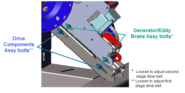
- Use a 1/2" socket to loosen first stage belt tensioner and walk the first stage drive belt off the pulleys. Remove the first stage drive belt. Retain belt for installation.
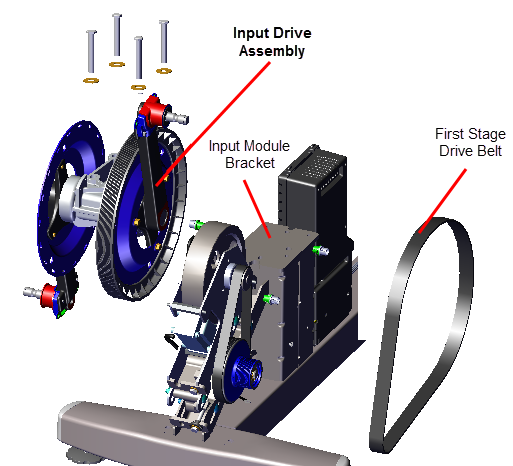
- Use a 9/16" socket to remove the four fasteners (bolts and washers) and remove the Input Drive Assembly. Discard the four Nylock bolt fasteners (these bolts cannot be reused for installation). Retain washers for installation.
|
|
CAUTION: Do not reuse the Input Assy Nylock patch bolt fasteners for installation. Discard the used bolts and order new bolts for installation (see Exploded View Diagrams, bubble # 296). |
Installation Instructions
- Reinstall the Input Drive Assembly onto the weldment input module mounting bracket and secure using four NEW Nylock patch bolt fasteners (see Exploded View Diagrams, bubble # 296). The removed washers can be reused for installation. TorqueTorque is a measure of the force that can cause an object to rotate about an axis. Bolt/nut example: 5 nM torque is equivalent to 5 newtons of force applied one meter from the center of the bolt, 6 ft-lb is equivalent to 6 lb of force applied 1 foot away from the center of the bolt. to 300 +/- 90 in-lbs (34 +/- 10 Nm).
|
|
CAUTION: Do not reuse the Crank and Input Bearing Assy Nylock patch bolt fasteners for installation. Discard the bolts and order new bolts for installation (see Exploded View Diagrams, bubble # 296). |
- Adjust the first stage tensioner as necessary to walk the first stage drive belt onto the Input drive and smaller first stage drive pulleys. Rotate the crank and make sure that the belt is properly aligned and seated in the pulley grooves.
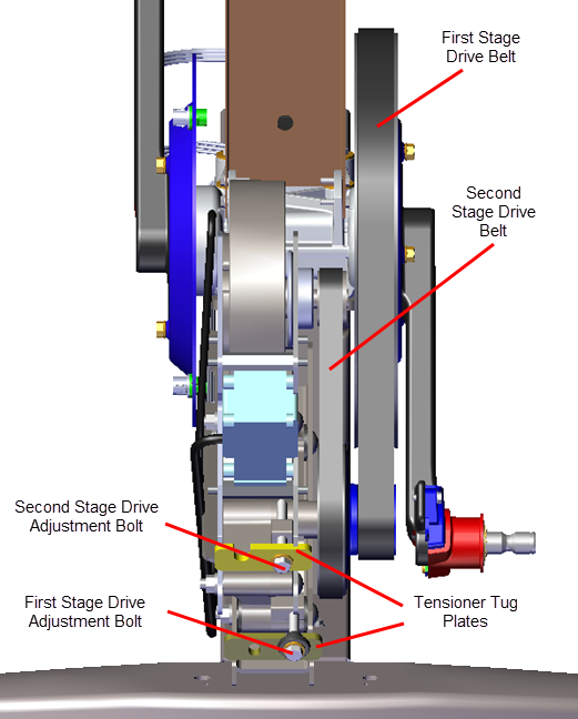
- Tension the first stage drive belt to 140-150 lbs (63.5 - 68 kgs), see First Stage Drive Belt Tension Adjustment.
- Verify that the second stage drive belt is within the specified tension 110-120 lbs (50- 54.4 kgs), see Second Stage Drive Belt Tension Adjustment. Retention belt if not within specification.
- Tighten the two Drive Components assembly carriage bolt fasteners, torque to 180 in-lbs (20.3 Nm).
- Reinstall the right and left Drive Housing and Drive Top covers (includes reinstalling the Stairarms), see Drive Housing Covers Replacement.
- If the Stairarms are not installed, reinstall the left and right Stairarms onto the Input Drive Crank, see Stairarm Replacement.
- Reinstall the left and right Drive Disk covers, Drive Disk Covers Replacement.
- Reinstall the Drive Access cover, Drive Access Panel Replacement.
- Verify machine operation and return to service, see Operation Verification.