Drive Components assembly Replacement
About
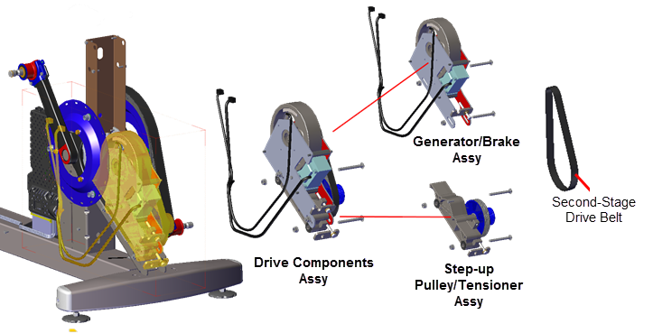
This procedure provides instruction to remove and install the Drive Components assembly.
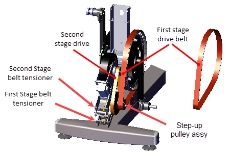
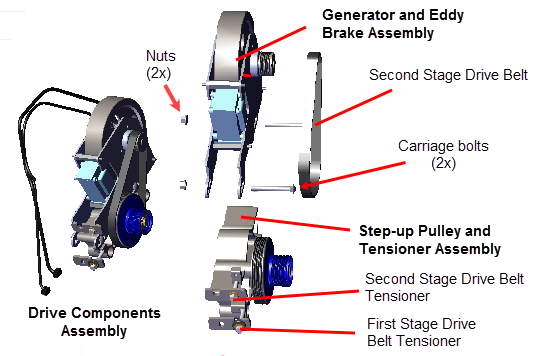
The Drive Components assembly consists of the Step-up Pulley/Tensioner assembly and Generator Eddy Brake assembly.
Procedure
Review entire procedure before starting.
Removal Instructions
- Remove the Drive Access cover, see Drive Access Panel Replacement.
- Remove the left and right Drive Disk covers, see Drive Disk Covers Replacement.
- Remove the left and right Stairarms from the Input Crank, see Stairarm Input Drive Crank Removal.
- Remove the Drive Top and left/right Drive Housing covers see Drive Housing Covers Replacement.
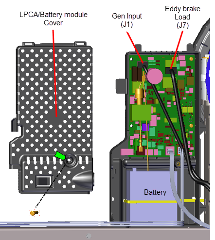
- Remove the one #2 Phillips screw fastener and LPCALower printed circuit assembly; generally this refers to the lower board. On treadmills, this is the motor controller unit (MCU), and on self-powered units, it is the main board in the lower section./Battery module cover. Disconnect the Generator input cable (J1) and Eddy/Brake load cable (J7) from the LPCA board. Retain part(s) and/or fastener(s) for installation.
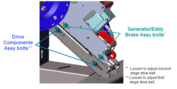
- Use a 1/2" socket to loosen the two Generator/Brake assembly and the two Drive Components assembly carriage bolt nuts (left side). Do not remove the carriage bolt nuts.
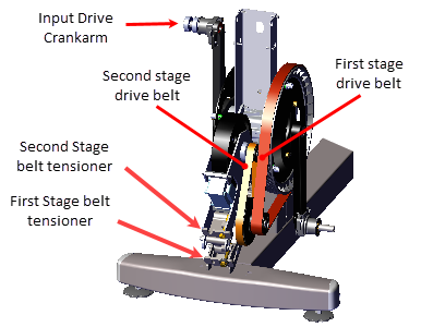
- Remove the second stage belt tension.by loosening the 1/2" second stage drive belt tensioner bolt.
- Use a 1/2" socket to loosen the first stage belt tensioner and walk the first stage drive belt off the Input Drive pulley and smaller first stage Step-up Pulley assembly pulley. Remove the first stage drive belt. Retain belt for installation.
- Use a 1/2" socket to remove the First Stage Tensioner hardware: the adjustment bolt (1x), washer (1x), bolt isolator (1x), and tug plate (1x). Retain part(s) and/or fastener(s) for installation.
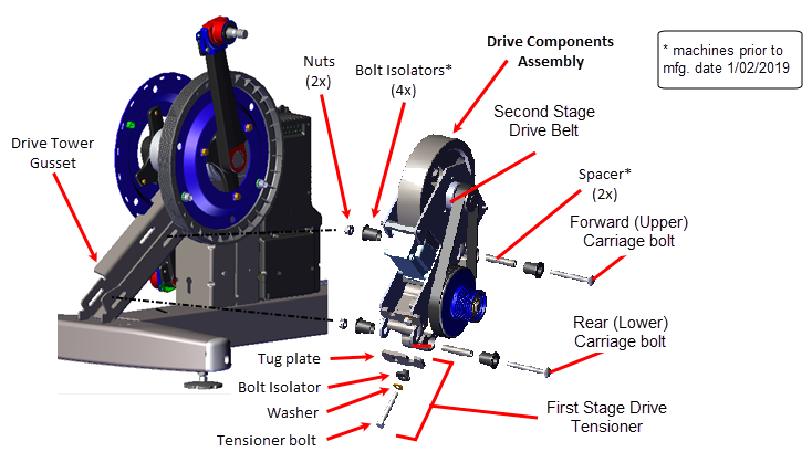
- Use a 1/2" socket to remove the two Drive Components assembly carriage bolts (2x) and nuts (2x). Remove the rear (lower) bolt first and then slide the Drive Components assembly downward to create room to remove the forward (upper) carriage bolt. Remove the Drive Components assembly. For machines with mfg. dates prior to 01/02/201, remove the bolt isolators (4x) and spacers (2x). Retain part(s) and/or fastener(s) for installation.
|
|
TIP: Machines with mfg. dates prior to 01/02/2019, the Step-up Pulley/Tensioner spacers (2x) and bolt isolators (4x) can easily fall out of the mounting bolt holes. Take care to keep track of these parts for installation. |
Installation Instructions
- If the Drive Components assembly is disassembled, reassemble as follows:
- Install the Generator/Brake assembly onto the Step-up Pulley/Tensioner assembly and secure using the two 1/2" Carriage bolts and nuts.
- Tighten the carriage bolts just enough to keep the carriage bolt heads inserted into the mounting slot but do not fully tighten.
- Walk the second stage drive belt onto the Generator/Brake assembly pulley and the larger second stage Step-up Pulley/Tensioner assembly pulley. Tighten the second stage tensioner just enough to hold the tensioner hardware and belt in position. The belt will be properly tensioned after the Drive Components assembly is installed.
- Position the Drive Components assembly onto the Drive Tower Gusset. For machines with mfg. dates prior to 01/02/2019, install the bolt isolators (4x) and spacers (2x) prior to installing Drive Components assembly.
- Slide the Drive Components assembly downward and install the upper (forward) carriage bolt and then slide the Drive Components assembly upward and install the lower (rear) carriage bolt. Tighten the carriage bolt nuts just enough to keep the carriage bolt heads inserted into the mounting slot but do not fully tighten.
- Use a 1/2" socket to install the First Stage Tensioner hardware: the adjustment bolt (1x), washer (1x), bolt isolator (1x), and tug plate (1x). Tighten the tensioner bolt enough to hold the hardware in place.
- Install the first stage drive belt by walking the belt onto the Input Drive pulley and the smaller first stage Step-up Pulley/Tensioner assembly pulley Rotate the crank and make sure that the belt is properly centered and seated in the pulley grooves.
- Tension the first stage drive belt, see First Stage Drive Belt Tension Adjustment.
- Tension the second stage drive belt, see Second Stage Drive Belt Tension Adjustment.
- Tighten the two Generator/Eddy Brake assembly and two Drive Components assembly carriage bolt fasteners, torque to 180 in-lbs (20.3 Nm).
- Reconnect the Generator input cable (J1) and Eddy/Brake load cable (J7) on the LPCA board. Reinstall the LPCA/Battery module cover and secure with the #2 Phillips screw fastener.
- Reinstall the right and left Drive Housing and Drive Top covers, see Drive Housing Covers Replacement.
- Reinstall the left and right Stairarms onto the Input Drive Crank, see Stairarm Input Drive Crank Installation.
- Reinstall the left and right Drive Disk covers, Drive Disk Covers Replacement.
- Reinstall the Drive Access cover, see Drive Access Panel Replacement.
- Verify machine operation and return to service, see Operation Verification.
See Also
Second Stage Drive Belt Tension Adjustment
First Stage Drive Belt Tension Adjustment