Generator/Eddy Brake assembly Replacement
About
This procedure provides instruction to remove and install the Generator/Eddy Brake assembly.
Procedure
Review entire procedure before starting.
Removal Instructions
- Remove the Drive Access cover, see Drive Access Panel Replacement.
- Remove the left and right Drive Disk covers, see Drive Disk Covers Replacement.
- Remove the left and right Stairarms from the Input Crank, see Stairarm Input Drive Crank Removal.
- Remove the Drive Top and left/right Drive Housing covers see Drive Housing Covers Replacement.
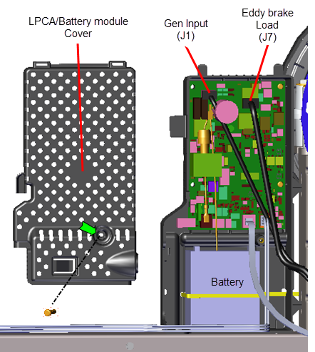
- Remove the one #2 Phillips screw fastener and LPCALower printed circuit assembly; generally this refers to the lower board. On treadmills, this is the motor controller unit (MCU), and on self-powered units, it is the main board in the lower section./Battery module cover. Disconnect the Generator input cable (J1) and Eddy/Brake load cable (J7) from the LPCA board. Retain part(s) and/or fastener(s) for installation.
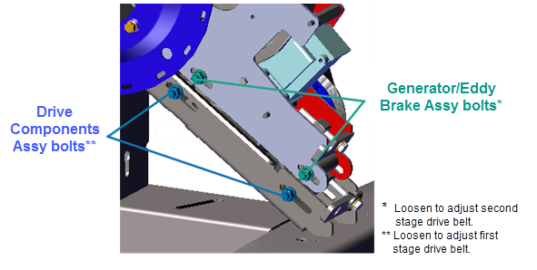
- Use a 1/2" socket to loosen the two Generator/Eddy Brake assembly carriage bolt nuts and the two Drive Components assembly carriage bolt nuts (left side). Do not remove the fastener nuts.
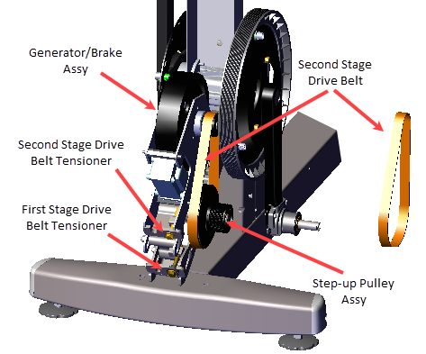
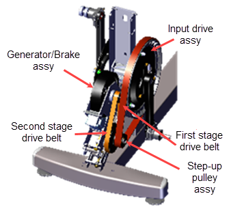
- Use a 1/2" socket to loosen the first stage belt tensioner and walk the first stage drive belt off the smaller first stage Step-up Pulley. Rest the belt on the input drive pulley, it is not necessary to remove the belt from the input drive.
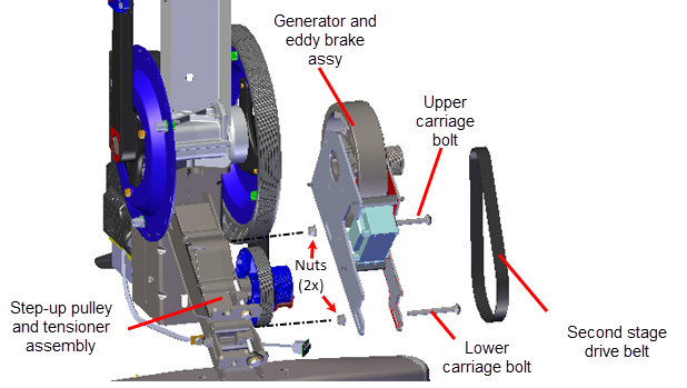
- Use a 1/2" socket to loosen the second stage belt tensioner and walk the second stage drive belt off the Generator/Eddy Brake assembly pulley and larger second stage Step-up Pulley/Tensioner assembly pulley. Remove the second stage drive belt. Retain belt for installation.
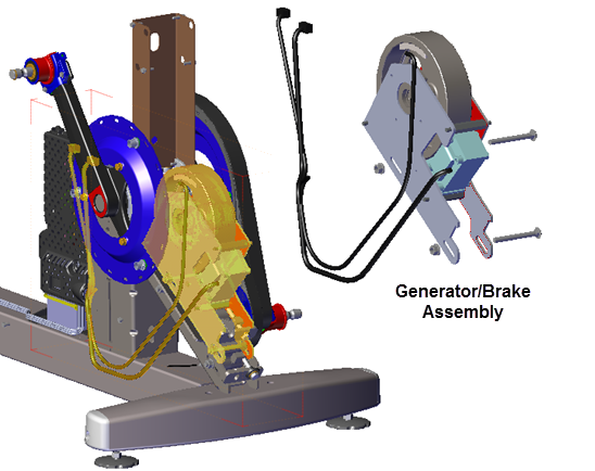
- Use a 1/2" socket to remove the Generator/Eddy Brake assembly lower carriage bolt. Then slide the Generator/Eddy Brake assembly downward and remove the upper carriage bolt. Remove the Generator/Eddy Brake assembly from the Step-up Pulley/Tensioner assembly. Retain part(s) and/or fastener(s) for installation.
|
|
TIP: Remove the lower carriage bolt fastener first and then the upper. The upper bolt cannot be removed while the lower bolt is installed. |
Installation Instructions
- Position the Generator/Eddy Brake assembly onto the Step-up Pulley/Tensioner assembly.
- Slide the Generator/Eddy Brake assembly downward and install the upper carriage bolt. Tighten the bolt just enough to keep the carriage bolt head inserted into the mounting slot but do not fully tighten. Then slide the assembly upward and install the lower carriage bolt. Tighten the bolt just enough to keep the carriage bolt head inserted into the mounting slot but do not fully tighten.
|
|
TIP: Install the upper carriage bolt fastener first and then the lower. The upper bolt cannot be installed when the lower bolt is installed. |
- Walk the second stage drive belt onto the Generator/Eddy Brake assembly pulley and larger second stage Step-up Pulley/Tensioner assembly pulley.
- Walk the first stage drive belt onto the smaller first stage Step-up Pulley assembly and Input Drive assembly pulleys and tension the belt to 140-150 lbs (63.5 - 68 kgs), see First Stage Drive Belt Tension Adjustment.
- Tension the second stage drive belt to 110-120 lbs (50- 54.4 kgs), see Second Stage Drive Belt Tension Adjustment.
- Fully tighten the two Generator/Eddy Brake assembly and two Drive Components assembly carriage bolts, torque to 180 in-lbs (20.3 Nm).
- Route and reconnect the Generator cable and Eddy/Brake cable to the LPCA Generator input (J1) and Eddy/Brake load (J7) I/OInput and Output Interface. connectors. Reinstall the LPCA/Battery module cover and secure with the #2 Phillips screw fastener.
- Reinstall the right and left Drive Housing and Drive Top covers, see Drive Housing Covers Replacement.
- Reinstall the left and right Stairarms onto the Input Drive Crank, see Stairarm Input Drive Crank Installation.
- Reinstall the left and right Drive Disk covers, Drive Disk Covers Replacement.
- Reinstall the Drive Access cover, see Drive Access Panel Replacement.
- Verify machine operation and return to service, see Operation Verification.