Lift Motor Replacement
About
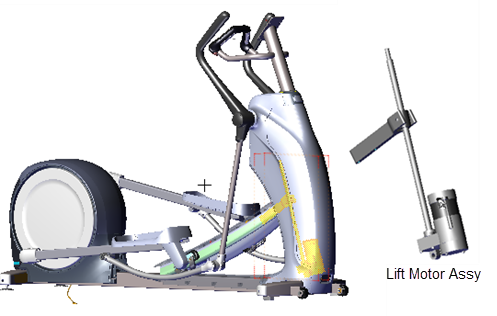
This procedure provides instruction to remove and install the Lift Motor.
Specifications
| System Component | Specification |
|---|---|
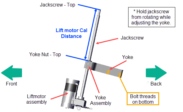
| Lift Motor Calibration Distance* | 9" +/- 1/4" (23 cm +/- 0.6 cm |
| Yoke/Ramp Fasteners | 330 in-lbs (27.5 ft-lbs or 37.2 Nm) |
| Note: * Calibration distance is set at incline level 10. | |
Lift motor power
Lift motor power is supplied by the battery thru the lift motor fuse located on the LPCALower printed circuit assembly; generally this refers to the lower board. On treadmills, this is the motor controller unit (MCU), and on self-powered units, it is the main board in the lower section. board, see LPCA Fuse Locations.
Procedure
Review entire procedure before starting.
Removal Instructions
- Remove the Front Lift cover, Lift Interface Plate cover, and Ramp cover, see Front Lift Cover Replacement, Lift Interface Plate Cover Replacement, and Ramp Cover Replacement.
- Place a protective pad over the top of the Front Frame Cover underneath the Ramp to protect the cover surface while doing this procedure.
- If the lift motor is working, access the CrossRamp Test diagnostic test and raise the incline level to 10
- P10, P30, P30i and P31: Service menu (51765761) > MACHINE TEST > CROSSRAMP > the INCLINE Level to 10.
- P62, P80, and P82: Service menu (51765761) > System Settings > System Tests > CrossRamp Test > raise the INCLINE level to 10.
|
|
CAUTION: Be careful to NOT jam the ramp when operating the incline level in CROSSRAMP TEST mode and there is an active lift error code (E40, E42, E45, or E46). There are no software position min/max limit stops in this mode of operation to prevent over extending the ramp beyond the upper and lower Limits. |
- Disconnect the Lift Motor input power/control cable.
|
|
WARNING: Make sure to disconnect the Lift Motor input power/control cable or it is possible for the ramp to automatically lower to level 1 under certain circumstances, such as, if the CrossRamp Test is exited or the console powers down and then the pedals are moved. This unexpected action could cause personal injury. |
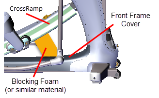
- Place blocking material (hard foam or similar material) between the underside of the ramp and front frame cover to support and keep the ramp in the raised position while doing the replacement procedure.
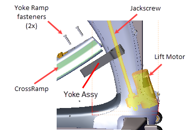
- Use a 9/16" socket to remove the two ramp-yoke fasteners and remove the yoke from the ramp. Take Note that the ramp will fall when the fasteners are removed. Make sure the ramp is supported before removing the fasteners. Retain part(s) and/or fastener(s) for installation.
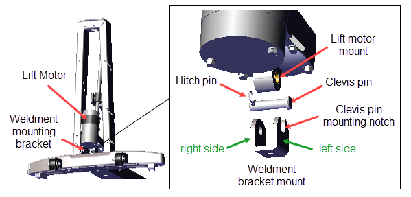
- Remove the hitch pin from the Lift Motor clevis pin. Then, while holding the lift motor assembly, slide the clevis pin to the left just enough to clear the bracket right side bolt hole. Then tilt the lift motor assembly forward enough for the jackscrew to clear the inside of the frame tower weldment and then lift to remove. Do not fully remove the clevis pin to remove the Lift Motor Assembly. Retain part(s) and/or fastener(s) for installation.
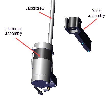
- Unscrew the Yoke Assembly from the jackscrew and remove. Retain the Yoke Assembly for installation
.
Installation Instructions
- Lay the replacement Lift Motor on the floor in front of the elliptical and connect the input power/control cable.
- .If the lift motor is working, access the CROSSRAMP TEST diagnostic test and raise the crossramp incline to level 10.
- .On LED (P10, P30, P30i and P31) consoles: Access diagnostic test menu (51765761) and select MACHINE TEST > CROSSRAMP TEST.
- .On touchscreen (P62, P80, and P82) consoles: Access the Service menu (51765761) and select System Settings > Systems Test > CrossRamp Test.
- Disconnect the input power/control cable.
- Install and calibrate the lift motor.
- While installing and/or adjusting the Yoke assembly on the jackscrew, do not allow the jackscrew to rotate invalidating the lift motor level 10 jackscrew calibration position. If the jackscrew does rotate, reconnect the lift motor power cable, reset the lift motor incline level to 10 and repeat the Lift Motor Yoke calibration.
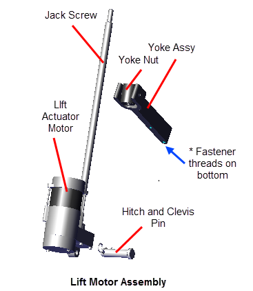
- Install the Yoke assembly onto the jackscrew with the yoke ramp mounting bolt threads positioned on the bottom side of the yoke. Use one hand to hold the jackscrew from rotating and the other hand to screw the Yoke Assembly onto the jackscrew.
- Adjust the Yoke so the distance from the top of the jackscrew to the top of the Yoke Nut is as close to the 9" +/- 1/4" (23 cm +/- 0.6 cm calibration distance as possible with the yoke direction pointing to the back (opposite the lift motor).
|
|
Note: Make sure to install the Yoke Assy with the ramp mounting bolt threads on the bottom of the yoke. |
- Install the lift motor:
- Insert the clevis pin from the left side of the lift motor mount until it is flush with the right side of the mount (do not allow the clevis pin to exit the right side of the lift motor mount bolt hole).
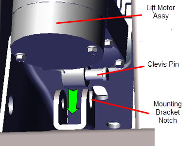
- Then install the lift motor assembly onto the lift motor weldment bracket so that the clevis pin rests in the left side mounting bracket notch.
- Tilt the lift motor assembly into the front tower weldment while carefully guiding the Yoke and jackscrew into mounting position.
- Next push the clevis pin completely through the right side of the weldment mounting bracket and secure with the hitch pin.
- Reattach the Yoke to the Ramp using the two fasteners, torque to 330 in-lbs (27.5 ft-lbs or 37.2 Nm).
- Remove any blocking materials and/or pads.
- Reconnect the Lift Motor input power/control cable.
- Access the service menu diagnostic CrossRamp Test and operate the ramp incline level through the full range of motion from minimum to maximum levels and verify operation:
- P10, P30, P30i and P31: (Service menu (51765761) > MACHINE TEST > CROSSRAMP TEST.
- P62, P80, and P82: (Service menu (51765761) > System Settings > System Tests > CrossRamp Test.
- Verify the lift motor calibration distance:
- Access the diagnostic CROSSRAMP TEST and set the incline level to 10.
- Measure and verify the Lift Motor calibration distance remains 9" +/- 1/4" (23 cm +/- 0.6 cm.
- Select QUICKSTART and start a manual workout. Operate the machine at the following conditions to verify the Stairarm and ramp incline operation. Make sure that the Stairarms and ramp movement is smooth and that there are no unusual noises:
- . Set the INCLINE to 1 and operate the machine from 50 to > 150 SPM.
- Repeat this test at incline levels 10 and 20.
- Reinstall the Ramp cover, the Lift Interface Plate cover, and the Front Lift cover, see Front Lift Cover Replacement, Lift Interface Plate Cover Replacement, and Ramp Cover Replacement.
- Verify machine operation and return to service, see Operation Verification.
|
|
Note: This procedure may have generated lift motor related error codes. Check the error log and resolve any active error codes, clear the error log on LED consoles. |
See Also