Second Stage Drive Belt Replacement
About
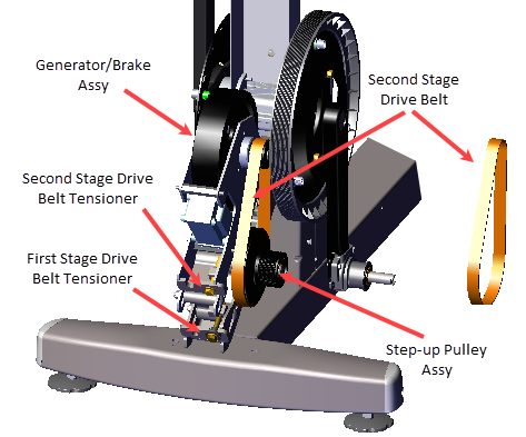
This procedure provides instruction to remove and install the Second Stage Drive Belt for a Dual Stage Input Drive Assembly.
Specifications
| System Component | Specification |
|---|---|
| Second Stage Belt Drive Tension - New(1) | 110-120 lbs (50- 54.4 kgs) |
| Second Stage Belt Drive Tension - Used(1) | 92 - 105 lbs (43 - 47.6 kgs) |
| Drive Component Assy Carriage Bolts | 180 in-lbs (20.3 Nm) |
| (1) New belt tension applies to new belt first time installations. Used belt tension applies to reinstalling an existing belt or re-tensioning an existing used belt. | |
Procedure
Review entire procedure before starting.
Removal Instructions
- Remove the Drive Access panel, see Drive Access Panel Replacement.
- Remove the right and left Drive Disk coves, see Drive Disk Covers Replacement.
- Remove the right Stairarm, see Stairarm Replacement.
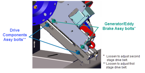
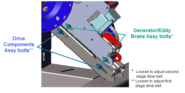
- Use a 1/2" socket to loosen the two Generator/Eddy Brake assembly and the two Drive Components assembly carriage bolt nuts (left side). Loosen the nuts just enough to allow movement but keep the carriage bolt heads inserted into the adjustment slots. Do not remove the fastener nuts.
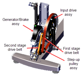
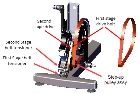
- Use a 1/2" socket to loosen the first stage belt tensioner and walk the first stage drive belt off the input drive and smaller Step-up Pulley/Tensioner assembly pulleys. Remove the first stage drive belt.
- Use a 1/2" socket to loosen the second stage belt tensioner and walk the second stage drive belt off the Generator/Eddy Brake and larger Step-up Pulley/Tensioner assembly pulleys. Remove the second stage drive belt.
Installation Instructions
- Install the second stage drive belt by walking the belt onto the Generator/Brake assembly and larger second stage Step-up Pulley/Tensioner assembly pulleys. Rotate the crank and make sure that the belt is properly aligned and seated on both pulley grooves. Adjust the second stage tensioner just enough to hold the tensioner mechanism and belt in place.
- Install the first stage drive belt by walking the belt onto the input drive and smaller first stage step-up pulleys. Rotate the crank and make sure that the belt is properly aligned and seated in the pulley grooves. Adjust the first stage tensioner just enough to hold the tensioner mechanism and belt in place.
- Adjust the first stage drive belt tension to specification, see First Stage Drive Belt Tension Adjustment .
- Use a 1/2" socket to fully tighten the two Drive Components assembly bolts. TorqueTorque is a measure of the force that can cause an object to rotate about an axis. Bolt/nut example: 5 nM torque is equivalent to 5 newtons of force applied one meter from the center of the bolt, 6 ft-lb is equivalent to 6 lb of force applied 1 foot away from the center of the bolt. bolts to 180 in-lbs +/- 54 (20.3 +/_ 4.5 Nm).
- Adjust the second stage drive belt tension to specification, see Second Stage Drive Belt Tension Adjustment.
- Use a 1/2" socket to tighten the two Generator/Eddy Brake assembly and the two Drive Components assembly carriage bolts. Torque both bolts to 180 in-lbs +/- 54 (20.3 +/_ 4.5 Nm).
- Reinstall the right Stairarm, see Stairarm Replacement.
- Reinstall the right and left Drive Disk coves, see Drive Disk Covers Replacement.
- Reinstall the Drive Access panel, see Drive Access Panel Replacement,
- Verify machine operation and return to service, see Operation Verification.