Data COMM Cable Replacement
Applies To: (Spinner® ChronoSpinner® Chrono™ Power bike.™ Power models only)
About
This procedure provides instruction to remove and install the Data COMM cable.
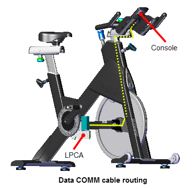
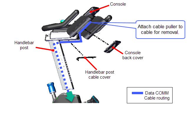
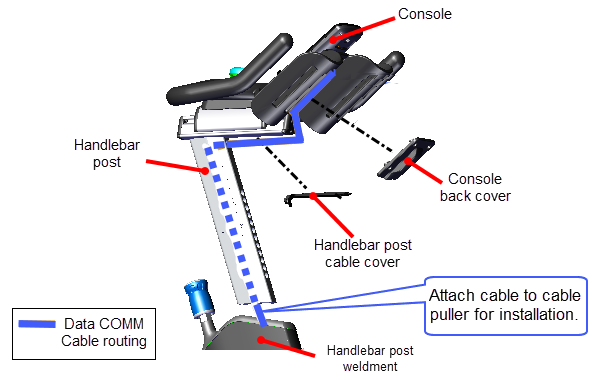
Data COMM cable routing
Starting from the console connection, the Data COMM cable enters and travels down the handle bar post continuing down the inside of the right fork weldment exiting the lower cable access hole located next to the upper edge of the cross member. The cable continues rearward on the right side of the cross member crossing over to the left side connecting to the LPCALower printed circuit assembly; generally this refers to the lower board. On treadmills, this is the motor controller unit (MCU), and on self-powered units, it is the main board in the lower section. Data COMM cable port.
Specialized Tools
| Tool | Part Number | Qty | |
|---|---|---|---|
| Magnetic Gap Fixture kit* |
|
PPP000000058248101 | 1* |
| Cable Puller (fish tape)** |

|
General purpose** | 2 |
|
Note: * Each Magnetic Gap Fixture kit contains two (2x) Magnetic Gap Fixture tools. |
|||
Parts
| QTY | Part Number | Description | Image |
|---|---|---|---|
| 2 | PPP00RX2809393M000 | Push Mount Cable Tie |
|
| 4 | General purpose | Cable Zip Tie (6 - 8 in) |
|


Procedure
Review entire procedure before starting.
Removal
- Remove front and rear belt guard covers, see Belt Guard Cover Replacement.
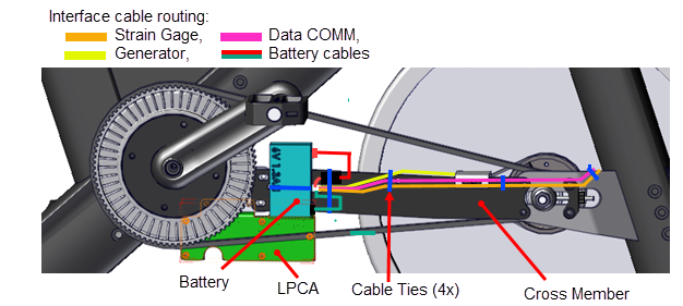
- Cut the four cross member cable-ties (4x) that secure the Data COMM, strain gauge, generator, and battery cables to the cross member. Discard the cable ties.
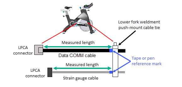
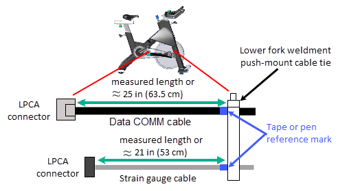
- Disconnect the Data COMM, Strain Gauge, Battery, and Generator cables. Use a pen or tape to mark the Data COM and Strain Gauge cables at the lower fork push mount cable tie.
|
|
Note: Alternatively you can measure and record the Data COMM cable and Strain Gauge cable lengths from the LPCA connectors to the right fork lower push-mount cable tie. The reference marks (or measured cable lengths) will be used during the installation process. |
- Remove the flywheel which requires removing the LPCA board, the cross member, drive belt, and generator belt, see Drive Belt, Generator Belt, and Flywheel Replacement.
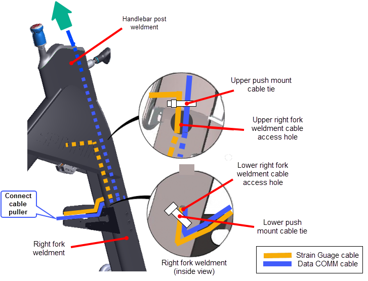
- Carefully cut and remove the upper and lower push mount cable ties (2x) that secure the strain gauge and Data Comm cables to the inside of the right fork frame weldment. Discard the push mount cable ties.
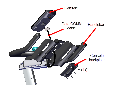
- Remove the four 4 mm (4x) hex key bolts and remove the console backplate cover. Disconnect the Data COMM cable from the console and set the console aside, see the "SPINNER® CHRONO™ CONSOLE" Operator's Guide.
- Remove the Data COMM cable from the handlebar assembly:
- Remove the two 2.5 mm hex key bolts (2x) and remove the handlebar post cable cover.
- Attach a cable puller to the Data COMM cable console connector.
- Pull the handlebar height adjust pop pin and carefuly lift the handlebar post from the top of the frame weldment. While holding the handlebar assembly, gently pull the Data COMM cable (and attached cable puller) downward and out from the inside of the handlebar post.
- Disconnect the Data COMM cable from the cable puller leaving the cable puller inside the handlebar post and set the handlebar assembly aside. The cable puller will be used to reinstall the cable through the inside of the handlebar post.
- Remove the Data COMM cable from the inside of the handlebar post and right fork weldment:
- Attach a cable puller to the Data COMM cable LPCA connector.
- Gently pull the cable (and attached cable puller) upward through the inside of the right fork weldment (thru the lower and upper fork weldment cable access holes) and out the top of the handlebar post weldment. Stop pulling when the cable puller exits the top of the handlebar post weldment. Disconnect the cable puller from the Data COMM cable leaving the cable puller inside the right fork weldment.
|
|
IMPORTANT: Attach a cable puller (or fish tape) to the LPCA connector end of the Data COMM cable before removing from the inside of the fork frame weldment. The cable puller will be used to reinstall the cable through the frame. |
Installation
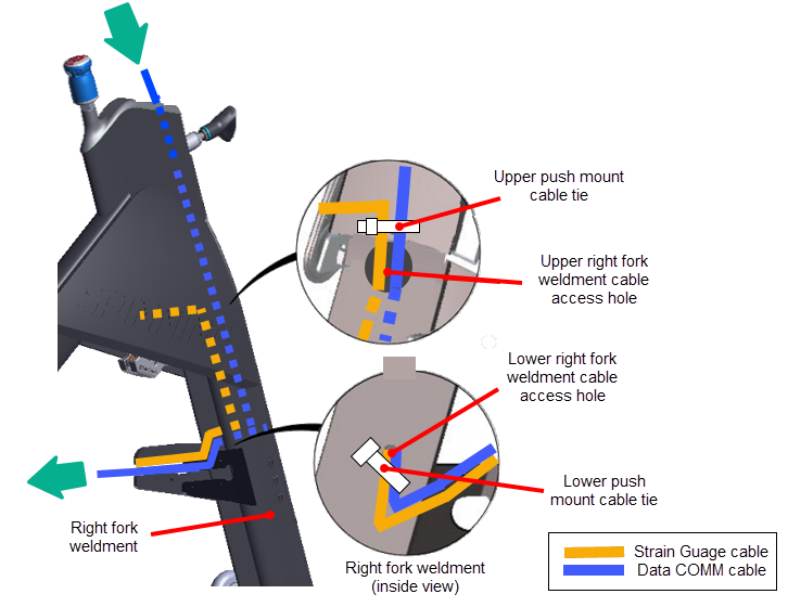
- Reinstall the Data COMM cable through the inside of the right fork weldment and out the top of the handlebar post weldment.
- Attach the Data COMM cable - LPCA connector to the previously installed cable puller exiting the top of the handlebar post weldment.
- Grasp the cable puller at the lower cable access hole and gently pull the cable puller downward through the inside of the handlebar post weldment and right fork weldment exiting though the lower right fork weldment cable access hole.
- Disconnect the cable puller from the Data COMM cable.
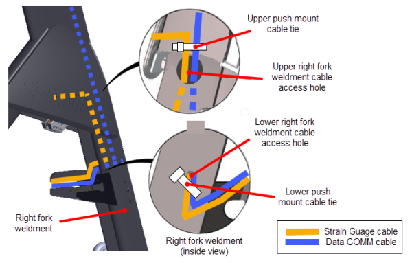
- Secure the Data COMM and Strain Gauge cables to the right fork weldment lower and upper push-mount cable ties: Secure the cables to the lower push-pin cable tie first and then to the upper push-pin cable tie.
- Install new upper and lower right fork weldment push‑mount cable ties (2x); one next to the upper right fork weldment cable access hole and one next to the lower right fork weldment cable access hole.
- Secure the Data COMM cable and Strain Gauge cables to the right fork weldment lower push-mount cable tie:
- Place the Data COMM cable and Strain Gauge cable into the right fork lower push-pin cable tie. Adjust each cable to the prior marked lower push-pin reference mark (tape or pen) and tighten the cable tie.
- Alternatively, adjust the Data COMM and Strain Gauge cable lengths to the prior measured length from the LPCA cable connectors to the lower push mount cable tie and then tighten the cable tie. If you did not make these measurements, adjust the Data COMM cable length to approx. 25 in (63.5 cm) and the Strain Gauge cable length to approx. 21 in (53 cm) and tighten the cable tie.
.
- Secure the Data COMM cable and Strain Gauge cables to the right fork weldment upper push-mount cable tie at the following conditions:
- Strain Gauge cable: Adjust the Strain Gauge cable so that there is a small amount of slack from the left caliper cable clip across the frame to the right side upper push-mount cable tie.
- Data COMM cable: Pull the Data COMM cable upward thru the upper fork weldment cable access hole until snug. Then secure the cable so that the cable slack will NOT touch or rub against the top of the fly wheel.
- When both cables are set to the install conditions, tighten the upper push-pin cable tie.
- Reinstall the Data COMM cable in the handlebar post:
- Connect the previously installed cable puller exiting the bottom of the handlebar post to the Data COMM cable - console connector.
- Lift the bottom of the handlebar assembly post next to the top of the handlebar post frame weldment.
- Grasp the cable puller and gently pull the Data COMM cable upward through the handlebar post. Continue pulling the cable while inserting the handlebar post into the handlebar post frame weldment. Be careful to not pinch or damage the Data COMM cable while installing the handlebar post.
- Use the handlebar height adjustment pop‑pin to secure the handlebar post in position.
- Reinstall the handlebar post cable cover using the two 2.5 mm hex key bolts (2x). Do not fully tighten the fasteners until after the console has been installed.
- Position the console on the dash and connect the Data COMM cable. Reinstall the console backplate and secure using the four 4 mm hex key bolts (4x) (see the "SPINNER® CHRONO™ CONSOLE" Operator's Guide). Make sure the Data COMM cable is not pinched or stretched too tight.
- Adjust the Data COMM cable slack from the console connector to the handlebar post slider until snug and fully tighten the handlebar post cable cover fasteners (2x). Slide extra slack into the handlebar post slider prior to tightening fasteners.
- Reinstall the flywheel, see Drive Belt, Generator Belt, and Flywheel Replacement.
- Hand rotate the pedals and verify that the Data COMM cable does NOT touch or rub against the top of the flywheel.
- If the cable rubs against the flywheel, the Data COMM cable slack must be readjusted so that the cable does not touch the flywheel. This may require removing the flywheel to make adjustments.
|
|
CAUTION: Make sure that the Data COMM cable does not rub against the top of the flywheel. Readjust cable slack as necessary. |
- Ride the bike and verify that the console powers on and is operating normally.
- Make sure the WATTS, RPM, TIME, DISTANCE, and INTERVAL metrics are reporting correct information.
- Access the service mode and review the ERROR LOG, see Error Log. Make sure there are no current logged error code 30s "Communication issue with the LPCA".
- Replace the front and rear belt guard covers, see Belt Guard Cover Replacement
- Verify the bike operation, see Operation Verification Checklist and return to service.
S