Drive Belt, Generator Belt, and Flywheel Replacement
Applies To: (Spinner® ChronoSpinner® Chrono™ Power bike.™ Power models only)
About
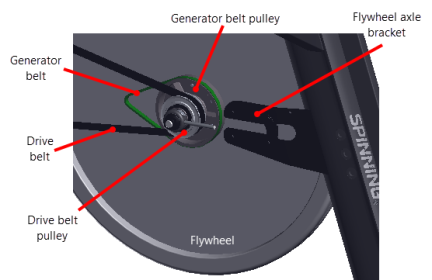
This procedure provides instruction to remove and install the Drive Belt, Generator Belt, and Flywheel.
Drive belt and generator belt replacement requires removal of the flywheel so this one procedure provides removal and installation procedures for the flywheel, drive belt and generator belt.
|
|
WARNING: Personal injury is possible while removing/installing the flywheel. The flywheel weighs approximately 26 lbs (12 kgs) and can pinch or fall onto fingers or other extremities causing personal injury. |
Specifications
| System Component | Specification |
|---|---|
| Drive Belt Tension | 60 +/- 5 lbs (27 */- 2 kgs) |
| Generator Belt Tension | 1/2 in (1.3 cm) up/dwn travel |
| Axle Nut TorqueTorque is a measure of the force that can cause an object to rotate about an axis. Bolt/nut example: 5 nM torque is equivalent to 5 newtons of force applied one meter from the center of the bolt, 6 ft-lb is equivalent to 6 lb of force applied 1 foot away from the center of the bolt. | 29.5 ft-lbs (40 Nm) |
| Flywheel Weight | 26 lbs (12 kgs) |
Procedure
Review entire procedure before starting.
Removal procedure
- Remove the front and rear belt guard covers, see Belt Guard Cover Replacement.
- Remove all brake pad resistance by turning the resistance knob fully counterclockwise (-).
- Remove the left and right brake pads, see Brake Pad Replacement.
- Disconnect the battery cable Black wire from the Negative (-) battery terminal and then the Red wire from the Positive (+) battery terminal, see Battery Replacement . Disconnect the battery Negative (-) terminal wire first:
-
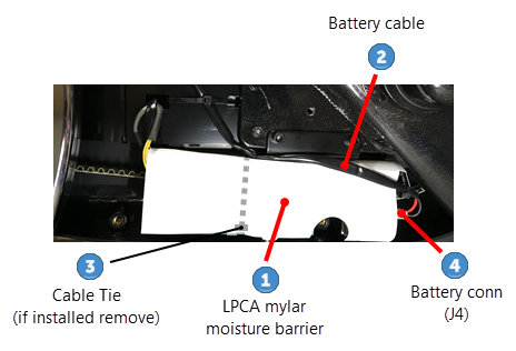
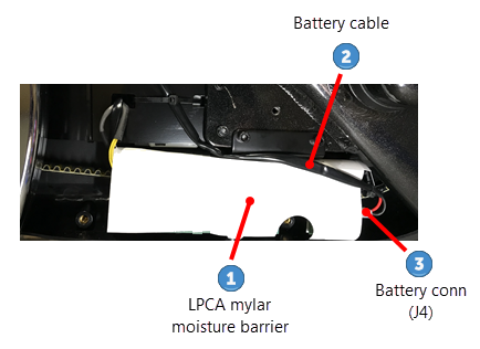
Disconnect the battery cable
 from the LPCALower printed circuit assembly; generally this refers to the lower board. On treadmills, this is the motor controller unit (MCU), and on self-powered units, it is the main board in the lower section. battery connector (J4)
  , see the following diagram. (If there is a LPCA moisture barrier
  cable tie
  installed, cut, remove, and discard.)
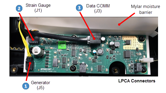
 - Lift the Mylar moisture barrier and disconnect the Generator (J5)
 cable connector, then the Data COMM (J3)
  cable connector and last the Strain Gauge (J1)
  cable connector.
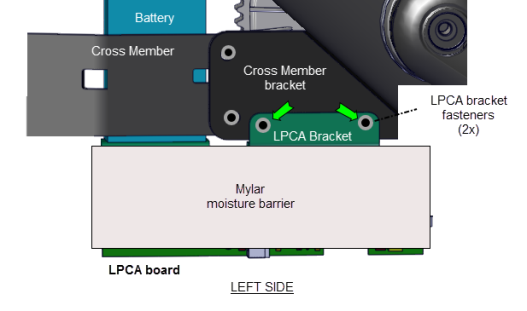
 - Remove the two 4 mm hex key LPCA bracket mounting bolts (2x) and washers (2x) and remove the LPCA bracket. Retain part(s) and/or fastener(s) for installation.
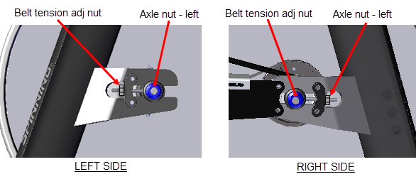
- Loosen, but do not remove, the left and right 17 mm axle nuts enough to allow flywheel axle movement.
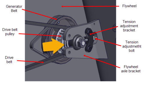
- Remove drive belt tension by alternately loosening the left and right tension adjustment nuts using a 10 mm wrench. Then fully remove the nuts and retain for installation.
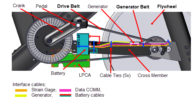
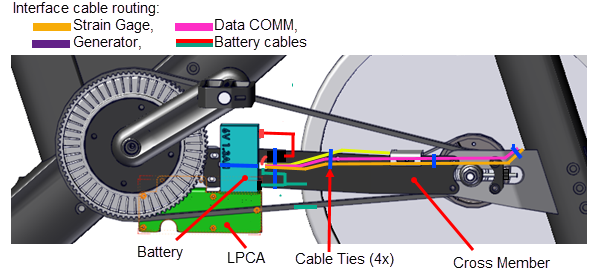
- Cut the back three cable-ties that secure the generator, data COMM, strain gauge (Spinner® Chrono™ Power models only), and battery cables to the cross member.

|
|
TIP: It is not absolutely necessary to remove the back three cable ties from the cross member during flywheel removal and installation. However, care must be taken to not damage the cables when setting the cross member to the side. |
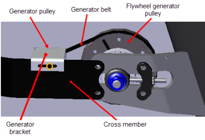
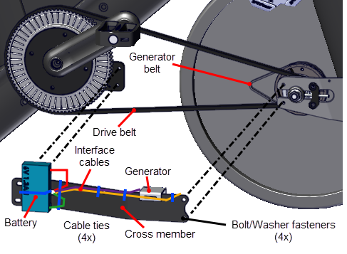
- Remove the frame cross member four 6 mm hex key bolts (4x) and washers (4x) and remove the cross member. Remove the generator belt from the generator pulley and then carefuly set the cross member to the side taking care to not damage the cables
- Remove the flywheel (weight: 26 lbs (12 kgs)) by carefuly sliding it rearward off the frame axle brackets.
|
|
WARNING: Personal injury is possible while removing/installing the flywheel. The flywheel weighs approximately 26 lbs (12 kgs) and can pinch or fall onto fingers or other extremities causing personal injury. |
Drive belt removal
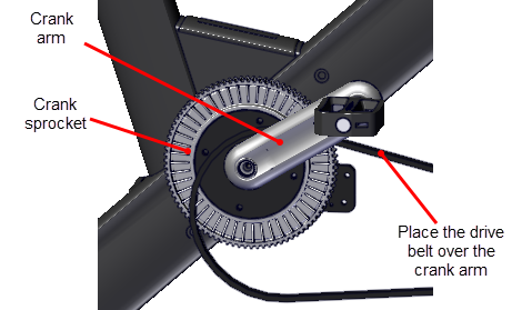
- Remove the drive belt by carefuly removing the belt off the flywheel pulley and then sliding the belt over the crank sprocket and pedal.
Generator belt removal
- Remove the generator belt from the flywheel generator pulley.
Installation procedure.
- Place the drive belt over the pedals and rest it on the crank.
- Position the flywheel in front of the flywheel axle bracket. Then put the generator belt onto the flywheel generator pulley and the drive belt onto the flywheel drive pulley.
|
|
IMPORTANT: The generator and drive belts must be placed onto the flywheel generator and drive belt pulleys before installing the flywheel onto the axle mounting bracket. |
- Reinstall the flywheel by carefuly sliding the flywheel axle into the frame axle brackets. The belt tension adjustment bolts need to be aligned so that they slide thru the bolt holes in the tension adjustment bracket.
|
|
TIP: You may find it is easier to stand the bike frame on its front (resting on the front stabilizer and handlebar) and then installing the flywheel into the axle mounting slots. The weight of the flywheel will help to slide the flywheel into the mounting slots. Carefully hold the flywheel and return bike to the upright position. |
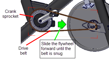
- Place the drive belt onto the crank sprocket and flywheel pulley.
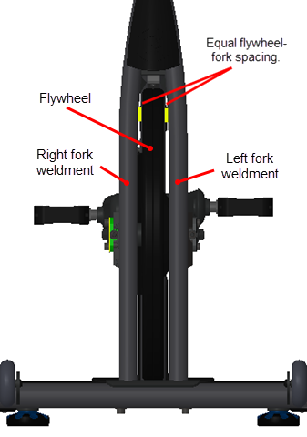
- Continue to slide the flywheel forward until the drive belt tension is snug and the belt teeth seat properly into the crank sprocket and flywheel pulley. Install the left and right tension adjustment bolts until snug. Adjust the left tension bolt so that the flywheel rim is centered between the left and right front forks (do not fully tension the belt at this step).
|
|
CAUTION: Thread the belt tension nuts onto the tension adjustment bolts to prevent the flywheel from accidentally falling off the flywheel axle bracket. |
- Reinstall the frame cross member using a 6 mm hex key to secure the four bolts (4x) and washers (4x). Fully tighten the four fasteners.
- Place the LPCA bracket into position on the frame cross member bracket and secure using the two 4 mm hex key bolts (2x) and washers (2x). Fully tighten the fasteners.
- Reconnect the Strain Gauge (J1) cable connector, then the Data COMM (J3) cable connector and last the Generator (J5) ,cable connector.
-
Fold the Mylar moisture barrier over the front of the LPCA and route the battery cable over the moisture barrier and reconnect to the LPCA battery cable connector (J4)
.
|
|
Note: The zip tie that removed and used to hold the Mylar moisture barrier over the LPCA board is not required to be replaced. |
- (Spinner® Chrono™ Power models only)
If the cross member cable ties were removed, replace them with new cable ties to secure the generator, data COMM, strain gauge , and battery interface cables to the cross member (4x locations). - Place the generator belt onto the generator and flywheel generator pulleys. Place the belt onto the smaller generator pulley and walk the belt onto the larger flywheel generator pulley
- Adjust the drive belt tension and tracking to specification, go to Drive Belt Tension and Tracking Adjustment
- If the axle nuts were not previously tightened to specification, tighten the left and right axle nuts torque to 29.5 ft-lbs (40 Nm).
-
Adjust the generator belt tension to 1/2 in (1.3 cm) up/dwn travel, see Generator Belt Tension Adjustment .
-
Install the left and right brake pads and adjust the brake pad gap to specification, see Brake Pad Replacement.
- Replace front and rear belt guard covers in reverse order, see Belt Guard Cover Replacement.
- Verify the bike operation per Operation Verification Checklist and return to service.