Lift Platform Replacement
About
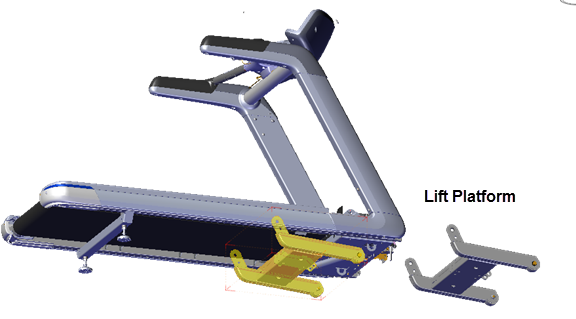
This procedure provides instruction to remove and replace the Lift Platform.
Procedure
Removal Instructions
Review entire procedure before starting.
- Remove the hood cover, see Hood Cover Replacement.
- Remove the left/right trim landing covers, see Trim Landing Covers Replacement.
- Remove the left and right trim side covers see Covers and Panels Replacement.
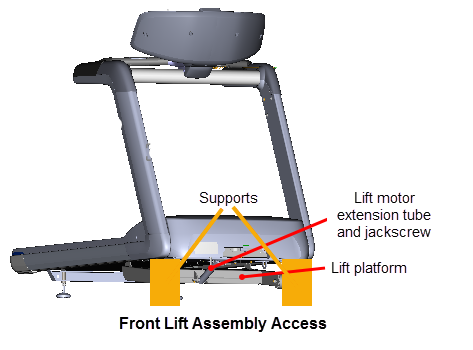
- You can access and remove the lift platform from the front of the treadmill or by laying the treadmill on its side. This procedure uses the front access method. If you do not have supports available, then use the alternative side access method, see Side lift platform assembly access procedure.
- Access the service menu (51765761) and select INCLINE TEST. Use the incline control to set the incline level to 14.
- Securely and safely place supports (e.g. car jack stands) under the left and right front corners of the frame weldment.
- Then lower the incline level in 0.5 increments until the lift platform wheels no longer touch the floor and the treadmill frame is completely resting on the supports. Keep the wheels as close to floor as possible without touching the floor making sure all the weight of the treadmill is carried by the supports. Verify the supports are stable and secure carrying the weight of the treadmill.
-
Use tape to mark the location of the extension tube on the jackscrew . Then remove the lift motor extension tube hitch pin and clevis pin fastener from the lift platform mounting bracket. Hold the lift platform while removing the clevis pin and carefully rest on the floor. Keep the extension tube from rotating while disconnecting from the mounting bracket. Retain part(s) and/or fastener(s) for installation.
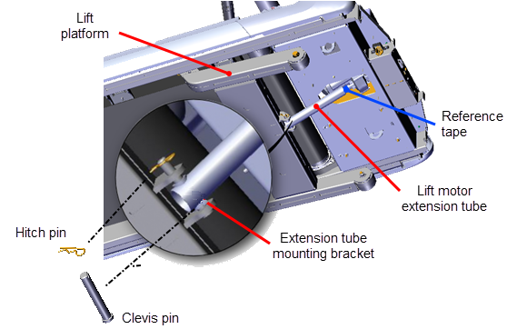
Do not allow the lift motor extension tube to move.
Make sure the lift motor extension tube does not rotate on the jackscrew during removal and remains at the same position for installation. Use tape to mark the extension tube position on the jackscrew . Allowing the extension tube to rotate will change the calibration distance nullifying the calibration. If the extension tube is rotated, recalibrate the lift motor before reinstalling.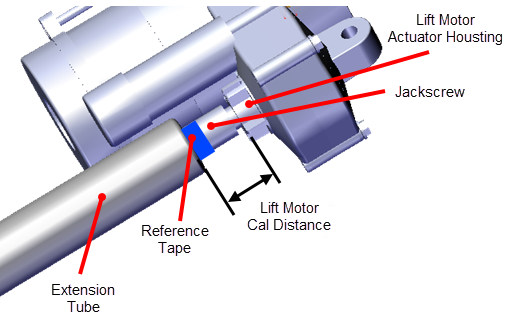
-
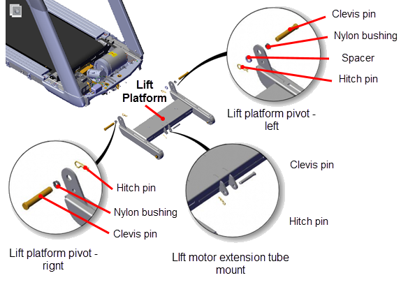
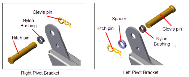
Remove right lift platform pivot hitch pin. Remove left lift platform pivot hitch pin and spacer. Carefully push the right and left clevis pins outward enough to allow the lift platform to be removed. Retain part(s) and/or fastener(s) for installation.
|
|
Note: You can alternatively access the lift platform assembly by laying the treadmill on its side, see Side lift platform assembly access procedure. |
Remove the lift platform
Installation Instructions
- Install the lift platform left and right pivot brackets into position and insert the right and left clevis pins. Add the spacer to the left clevis pin and secure using the hitch pin. Secure the right clevis pin with the hitch pin.
- Place the extension tube into the lift platform mounting bracket and secure using the hitch pin and clevis pin. It may be necessary to slightly rotate the extension tube to align the clevis pin mounting holes. If the extension tube has been rotated during or after it was removed, recalibrate the lift motor prior to installation, see Lift Motor Calibration.
Remove supports and lower the treadmill
- Connect the power cord and switch the power ON. Be aware that switching the power ON will cause the incline platform to move and return to the level "0" position. If you are using the side access method, see Side lift platform assembly access to upright the treadmill.
- Access the service menu (51765761) and select the INCLINE TEST. Increase the incline level enough to lift the treadmill frame off the supports.
- Remove the supports and clear any other items that might either block the treadmill from lowering or may be damaged as it lowers.
- Lower the incline to level "0".
- Verify the treadmill incline operation from minimum to maximum levels.Make sure that there are no active Incline function related error codes.
- Reinstall the left and right trim side covers see Covers and Panels Replacement.
- Reinstall the left/right trim landing covers, see Trim Landing Covers Replacement.
- Reinstall the hood cover, see Hood Cover Replacement.
- Do the Operation Verification tests (see Operation Verification) and return to service.
|
|
WARNING: Keep hands and appendages clear of the incline platform assembly before switching power ON. Switching power ON will cause the incline platform to move to the level "0" Home position. |