Motor Controller (MC) Replacement
About
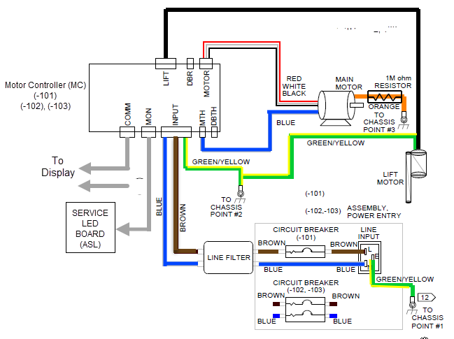
This procedure provides instruction to replace the Motor Controller (MCMotor controller or motor controller module).
The Motor Controller (MC), is located in the Drive Motor compartment at the front of the treadmill under the hood cover.
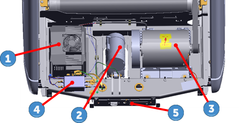
| ID | Description |
|---|---|
|
|
Motor Controller (MC) |
|
|
Lift Motor |
|
|
Drive Motor |
|
|
Line Filter |
|
|
Power Entry Assy Module |
MC I/O connectors
The MC interface input/output connectors are located on the front and back sides of the MC housing.
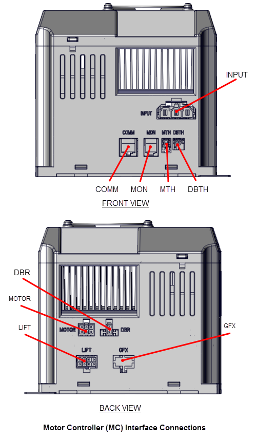
MC connector pin definitions
| CONN ID | NAME | PIN | Description |
|---|---|---|---|
| INPUT | MC ACAlternating Current: electric current which periodically reverses direction between positive and negative polarity. INPUT PWR | 1 | EARTH GROUND |
| 2 | AC LINE 1- LINE AC LINE | ||
| 3 | AC LINE 2- NEUTRAL | ||
| MOTOR | DRIVE MOTOR AC PWR OUT | 1 | MOTOR PHASE W |
| 2 | MOTOR PHASE V | ||
| 3 | MOTOR PHASE U | ||
| 4 | MOTOR PHASE W | ||
| 5 | MOTOR PHASE V | ||
| 6 | MOTOR PHASE U | ||
| COMM | CONSOLE INTERFACE CABLE | 1 | DIGITAL GROUND |
| 2 | +8 VDC | ||
| 3 | TCD DATA OUTPUT | ||
| 4 | DIGITAL GROUND | ||
| 5 | +8 VDC | ||
| 6 | RXD DATA INPUT | ||
| 7 | DIGITAL GROUND | ||
| 8 | E-STOP | ||
| DBR1) DB or DBR: treadmill dynmaic break resistor. 2) DB: power measured in decibles (dB).(1) | DYNAMIC BRAKE RESISTOR SENSE | 1 | THERMAL RESISTOR SENSE |
| 2 | THERMAL RESISTOR SENSE | ||
| MON | MONITOR (ASLActive Status Light: Service and maintenance status light. PCAPrinted circuit assembly, generally referred to as either an upper PCA or lower PCA. INTERFACE CABLE) | 1 | +8 VDC |
| 2 | /BOOT_EN | ||
| 3 | TX | ||
| 4 | 8V GND | ||
| 5 | D_RESET | ||
| 6 | RX | ||
| MTH | DRIVE MOTOR THERMAL SWITCH | 1 | THERMAL SWITCH SENSE |
| 2 | THERMAL SWITCH SENSE | ||
| DBTH(1) | DYNAMIC BRAKE RESISTER THERMAL SWITCH | 1 | THERMAL SWITCH SENSE |
| 2 | THERMAL SWITCH SENSE | ||
| LIFT | LIFT MOTOR PWR OUT & CONTROL | 1 | BLK - POTENTIOMETER |
| 2 | RED - POTENTIOMETER | ||
| 3 | NC | ||
| 4 | WHITE - MOTOR COMMON | ||
| 5 | WHITE - POTENTIOMETER WIPER | ||
| 6 | NC | ||
| 7 | RED - MOTOR EXTEND | ||
| 8 | BLK - MOTOR RETRACT | ||
| GFXGround Effects Impact Control System: Patented treadmill design that out performs a natural running surface, absorbs high-impact movement, reduces joint stress and minimizes fatigue and supports a solid and controlled push off. | not used | - | not used |
| Notes: 1) TRM800-14TRM800 version 2 treadmills mfg. dates 2014 and later. treadmills only. | |||
MC Fan Motor Connector
The fan motor interface cable connector is located under the MC top cover.
|
|
Note: For MC Fan replacement, see Motor Controller Fan Replacement. |
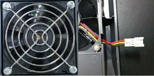
| Component | PIN | Description |
|---|---|---|
| Fan motor | 1 | Black (24V GND) |
| 2 | Yellow (Fault signal) | |
| 3 | Red (+24 Vdc) |
The MC status light is located on the left side of the MC housing.
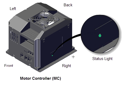
| ASL State | DESCRIPTION |
|---|---|
|
Green |
Normal operation. |
|
Yellow |
Indicates a fault condition has occured, refer to the error log for more information. The MC may continue to operate after a fault reset or there may be an internal MC fault that needs to be corrected before the MC will operate. The MC status light will not auto-reset after the fault is corrected, the MC status light must be reset to green from the hardware validation diagnostics menu. |
Review entire procedure before starting.
Removal Instructions
- Switch the power OFF and unplugDisconnect a device power cord plug or cable connector from the power receptacle or outlet. the power cord.
- Remove the hood cover, see Hood Cover Replacement.
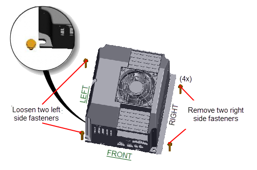
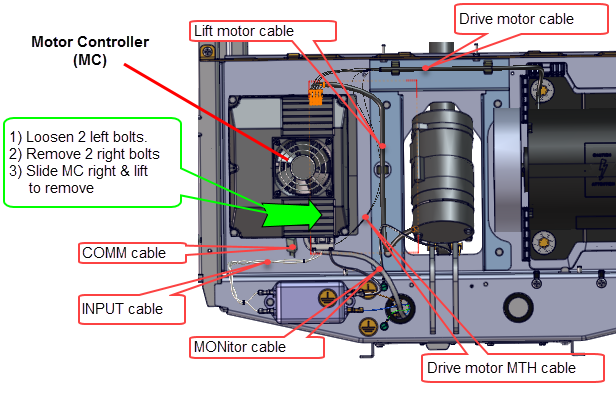
- Facing the front of the treadmill, remove the two right side 5/16" hex fasteners and then loosen the two left side 5/16" hex fasteners (approximately, 4 full turns). Slide the MC base to the right to remove. Retain part(s) and/or fastener(s) for installation.
- Carefully raise front and rear of MC as needed to disconnect the attached I/OInput and Output Interface. interface cable connectors, see Motor Controller (MC) Replacement.
|
|
Note: The COMM connector contacts have an application of dielectric grease to ensure proper electrical contact. Do not wipe off, clean, or remove the dielectric grease. |
Installation Instructions
- Place the MC into the drive motor compartment and reconnect the removed MC I/O cable connectors: LIFT motor cable, Drive MOTOR cable, COMM cable, MON ASL cable, Thermal switch MTH cable, power INPUT cable). It will be easier to attach the connectors before installing the MC into the mounting fasteners. Make sure the I/O cable connectors have the correct orientation and alignment before inserting into the receiving MC I/O port.
- Reinstall the MC by sliding the left side base flanges under the two left preinstalled loosened fasteners. Then install the two right side fasteners and fully tighten all four fasteners.
- Route cables and secure using the frame cable clamps. Recheck all cable MC connections and make sure that the cables have freedom of movement and clear of any frame or component edges that could pinch or damage the cable wires.
- PlugDevice power cord connector or electrical cable male connector that is inserted into an electrical receptacle "outlet" (also called the plug-in). in the power cord and switch the power ON.
- Verify the MC status light is green. If the status light is yellow, reset the status light as follows:
- Clear the Error Log of any stored error codes: Hold down PAUSE to access the Error Log > select OK to view error codes, and then hold down QUICK START to clear the Error Log of all error codes.
- Clearing the Error Log resets the ASL and MC status lights. Verify that the ASL status light is blue and the MC status light is green.
-
Reset the ASL and MC status lights: Access the service Settings menu (51765761), select Maintenance > Operating Condition > and the Reset softkey to reset the ASL and MC status lights. Verify the following Maintenance menu parameters:
- Recommended Action: None
- Operating Condition: Normal
- Active Status Light: Solid Blue
-
Visually verify that the MC status light is now “green” and the ASL light is “solid blue”.
-
Repeat selecting the Back softkey to exit and return to the “Welcome” banner home page.
- Reinstall the hood cover, see Hood Cover Replacement.
- Do the Operation Verification tests (see Operation Verification) and return to service.
|
|
CAUTION: Take your time and be careful when reconnecting the I/O cable connector plugs. Many of the connector contacts are small and can be easily damaged if incorrectly inserted into the receiving connector plug-in. |
P10, P30, P30i and P31
P62, P80, and P82
