Motor Controller Fan Replacement
About
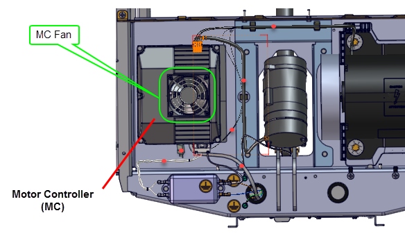
This procedure provides instruction to replace the Motor Controller (MCMotor controller or motor controller module) Fan.

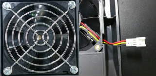
The fan motor interface cable connector is located under the MC top cover.

| Component | PIN | Description |
|---|---|---|
| Fan motor | 1 | Black (24V GND) |
| 2 | Yellow (Fault_signal) | |
| 3 | Red (+24 VDC) |
Review entire procedure before starting.
Removal Instructions
- Switch the power OFF and unplugDisconnect a device power cord plug or cable connector from the power receptacle or outlet. the power cord.
- Remove the MC, see Motor Controller (MC) Replacement.
-
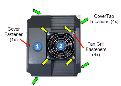
Use a #2 Philips screwdriver to remove the MC top cover
 screw fastener.
 -
Use a small standard screwdriver to release the four mounting tabs and carefully lift the MC top cover from the main housing. Disconnect the power cable connector and remove the top cover. Retain fastener for installation.
-
Use a #2 screwdriver to remove the four fan fasteners and remove the fan grill
 . Retain grill and fasteners for installation.
 -
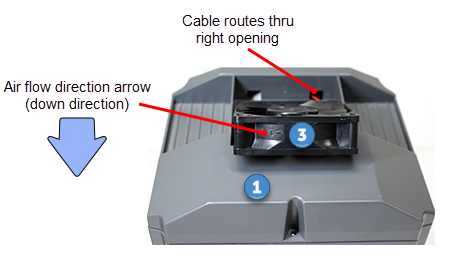
Carefully lift the fan
 and remove from top cover
  . Guide the power cable and connector through the cable routing opening while removing. Discard the fan.

Installation Instructions
- Make sure that the replacement fan is the most current part number (PPP000000304461101), see service bulletin SB.TRMTreadmill.20161014.
- The fan must be installed so the air flow is directed into the MC housing. Install the fan so that the embossed air flow indicator arrow points into the MC housing. If replacing the older fan with the newer fan, the new fan cable routing has changed. Feed the power cable thru the right cable housing opening (not the left opening) and install the new fan.
-
Reinstall the fan grill onto the fan and secure with the four screw fasteners.
-
Reconnect the fan power cable and install the top cover onto the MC housing. Make sure that the power cable is not pinched or damaged while snapping the top cover into the housing tabs. Secure top cover using the one screw fastener.
-
Reinstall the Motor Controller, see Motor Controller (MC) Replacement.
-
PlugDevice power cord connector or electrical cable male connector that is inserted into an electrical receptacle "outlet" (also called the plug-in). in the power cord and switch the power ON.
- P10, P30, P30i and P31 consoles
Clear the Error Log of any stored error codes: Hold down PAUSE to access the Error Log > select OK to view error codes, and then hold down QUICK START to clear the Error Log of all error codes.
Clearing the Error Log resets the ASLActive Status Light: Service and maintenance status light. and MC status lights. Verify that the ASL status light is blue and the MC status light is green.
- P62, P80, and P82 consoles
Reset the ASL and MC status lights: Select Operating Condition > press Reset softkey to reset the ASL and MC status lights. Verify the following Maintenance menu parameters:
Recommended Action: None
Operating Condition: Normal
Active Status Light: Solid Blue
-
Verify that the MC status light is now “green” and the ASL light is “solid blue”.
-
Exit service mode.
-
Press QUICK START to start a manual workout. Make sure the fan is running, that the air flows into the MC housing, and there are no error code 14 events.


|
|
Note:The fan will only run after the running belt is moving. |
- Reinstall the hood cover, see Hood Cover Replacement.
- Do the Operation Verification tests (see Operation Verification) and return to service.