Console Installation and Removal
About
This procedure provides instructions to remove and install the P82 console.
The console armor is designed to attach to cardio equipment bases ( including the EFXElliptical Fitness CrossTrainer, TRMTreadmill, AMTAdaptive Motion Trainer, and RBKRecumbent Bike/UBKUpright Bike bikes) that use a universal four bolt mounting plate. The number of interface cables that connect to the console will vary depending on the console type (standard or media adapter models) and the type of equipment.
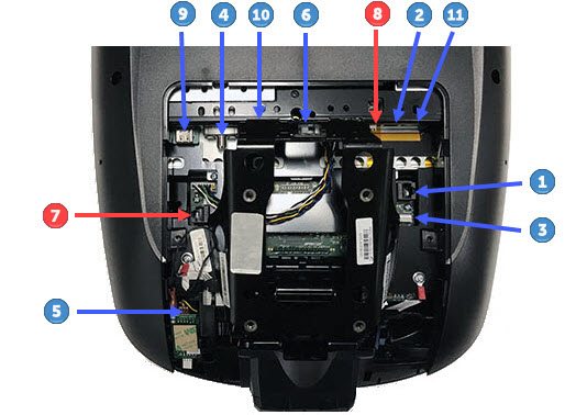
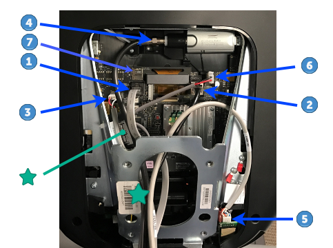
Console I/O Port Diagram
| CONNECTOR LOCATION |
INTERFACE DESCRIPTION |
CONNECTOR/DEVICE TYPE |
|---|---|---|
|
|
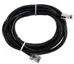
COMM Data Cable(1) | Black color RJ45 eight pin modular (flat gray Data cable). |
|
|
Ethernet (LAN) Cable(1) | Silver color RJ45 eight pin modular connector (round black LAN cable. |
|
|
E-Stop Switch Cable (TRM Only) |
Six pin strip, keyed. |
|
|
RF (TV) Cable with Isolator | F-Type coax |
|
|
HHHR Sensor Input Cable | Four pin strip, keyed. |
|
|
DC Input Power | Two pin plug (see  ) ) |
|
|
microSD mass storage | .microSD memory card |
|
|
Ferrite cable clamp | The input power cable must be looped thru the ferrite cable clamp. |
|
Notes: |
||
Removal Procedure
- If the console is operable, create a cloned system settings USBShort for Universal Serial Bus, is an industry standard developed in the mid-1990s that defines the cables, connectors and communications protocols used in a bus for connection, communication, and power supply between computers and electronic devices. flash drive, see Console Installation and Removal. This will save both the system settings and TV channel list to the USB drive. This USB drive will be used to configure the replacement console.
|
|
TIP: Creating a cloned system settings USB drive (exporting the system settings) allows you to clone (import system settings) the system settings and TV channel list to the replacement console. |
- Disconnect (or switch OFF) the console power:
- For treadmills, switch the ON/OFF circuit breaker OFF.
- For self-powered equipment, unplugDisconnect a device power cord plug or cable connector from the power receptacle or outlet. the console power supply input power cord.
- For treadmill installations, remove the treadmill dash back cover, see the treadmill Service Manual (download from the Precor Partner's website). Retain part(s) and/or fastener(s) for installation.
- Remove the console lower bezel cover, see P82 Console Cover Replacement. Retain bezel cover for installation.
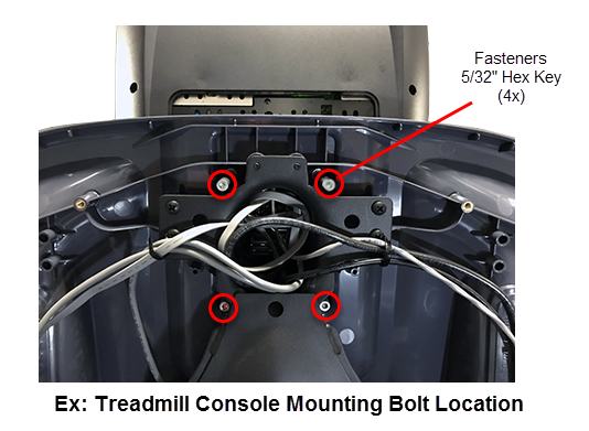
- Remove the four 5/32" (4 mm) hex key console mounting bolts. Retain part(s) and/or fastener(s) for installation.
|
|
Note: All Precor equipment bases use a four bolt console mounting plate to secure the console. Treadmills require the rear dash cover to be removed to access the console mounting fasteners. |
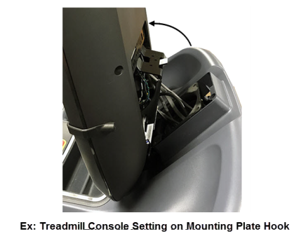
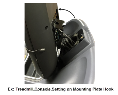
- Tilt the console rearward away from the dash and set the console armor onto the mounting plate hook.
- Carefully remove the console‑base interface cables. Disconnect the following cables, see P62 console I/O port diagram or P82 console I/O port diagram.
- E-Stop Safety Switch cable
 (Treadmills only).
 - COMM Data cable
 .
. - Ethernet (LAN) cable
 .
. - HHHR cable
 .
. - Power cable
 .
.- On P62 consoles, remove the cable from the ferrite cable clamp .
- On P62 consoles, remove the cable from the ferrite cable clamp
- RF (TV) Coax cable
 :
:- On P62 consoles, remove the RF cable from the TV tuner isolator (the isolator is part of the P62 TV tuner assembly)
- Media Adapter HDMI Video/Audio cable
 .
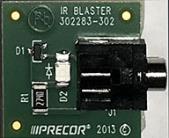
. - Media Adapter IR Blaster cable

Media Adapter Consoles
|
|
TIP: Before removing the cables, take a picture of the installed cable connections and routing. These pictures can be used as a guide to reinstall the cables. |
- Remove the console from the base.
Installation Procedure
Basic Installation Steps
Installing the console entails completing each one of the following basic steps:
- Locating the Interface Cables and Hardware (first time installations)
- Installing the Power Supply (first time installations or replacement).
- Installing the Console
- Updating the operating system software.
- Registering the console
- System Settings Setup (Display & Workout Limits)
- TV Channel Guide Setup
- Verify the console operation
Locating the Interface Cables and Hardware
(First time Installations only)
- Locate hardware and interface cables.
- Unpack the contents of the console shipping box:
- the Console
- the
 P82 Installation Guide (Literature kit package)
 - the accessory box (contains interface cables and hardware).
- Unpack the accessory box contents:
- the Ethernet (LAN) cable
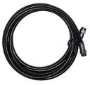
- the RF (TV) cable
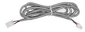
- the console power cable
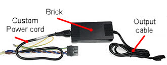
- the ACAlternating Current: electric current which periodically reverses direction between positive and negative polarity./DC power adapter brick
- the adapter brick input power cord (self-powered machine)
- the adapter brick input power adapter cable (treadmills)
- the adapter brick output power cable
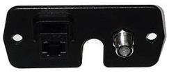
- the Entertainment Plate (Accessory Jack).
Media Adapter Consoles - the IR Transmitter interface cable
- the HDMI cable
- the IR Transmitter module.
- Unpack the contents of the console shipping box:
Cables and Hardware
|
|
|
|
| Ethernet LAN Cable | RF Coax Cable |
Entertainment Plate (Accessory Jack) |
|
||
| Power Cable |
|
|
|
|
| AC/DC Adapter (Self-powered machines) |
AC/DC Adapter (Treadmills) |
Media Adapter cables/hardware
|
|
|
|
| IR Transmitter Cable* | HDMI Cable* | IR Transmitter Module* | |
Installing the Power Supply
(First time Installation or power supply replacement only)
- Install the console power supply AC/DC adapter and cables:
Refer to the specific equipment Assembly Guide for instructions to install the console power supply AC/DC adapter and cables. You can download the assembly guide from the Precor.com website (go to the specific Cardio equipment home page, scroll down to the "Brochures and Manuals" drop down menu and select the equipment specific 800 Line Assembly Guide.
Installing the Console
This procedure installs the console onto the equipment base.
- For first time console installations, install the following console‑base I/O cables : the Ethernet cable , RF (TV) cable , and the entertainment plate on the base. Refer to the equipment Assembly Guide for instructions (download from the Precor.com equipment home page).
- For Media Adapter consoles, also install the IR Transmitter cable , HDMI cable , and IR Transmitter module. Refer to the Networked Fitness Media Adapter Guide for installation instructions (download from the "Experience™ Series P82 Console" home page (scroll down to the "Brochures and Manuals" select drop-down box and select Network Fitness Media Adapter Guide.).
- For Media Adapter consoles, also install the IR Transmitter cable
- For treadmill installations, remove the treadmill dash back cover to gain access to the console four mounting bolts, see the treadmill Service Manual (download from the Precor Partner's (Precor Connect) website.
- Remove the console lower bezel, see P82 Console Cover Replacement.
- Set the console armor onto the base mounting plate hook tilting rearward away from the dash. The hook holds the weight of the console and allows room to route and connect the interface cables.
- Install the following list of I/O interface cables. Hold the console while carefully routing and connecting the I/O interface cables, see Console I/O Port Diagram.
- RF (TV) Coax cable
:
- On P82 consoles, route the RF cable from the base mounting post upward through the console armor exiting through the upper left side, Connect the RF cable to the RF Tuner input . Do not over tighten the RF coax connector, torque to 2.4 in-lbs (0.271 Nm) (approx. finger tight).
- .On P62 consoles, route the RF cable from the base mounting post upward through the top left side of the console armor continuing up the left side bending right across the top of the armor opening connecting to the TV tuner isolator coax cable input (the isolator is part of the P62 TV tuner assembly). Do not over tighten the RF coax connector, torque to 2.4 in-lbs (0.271 Nm) (approx. finger tight).
- On P82 consoles, route the RF cable from the base mounting post upward through the console armor exiting through the upper left side, Connect the RF cable to the RF Tuner input
- Power cable :
 On P82 consoles, route the Power cable from the base mounting post upward through the console armor exiting through the top center connecting to the console DC Power input port . On P62 consoles, single loop the power cable through the ferrite cable clamp exiting the top of the armor connecting to the input power port . Open the ferrite cable clamp and loop the power cable around and through the clamp one time then snap the clamp cover closed to secure the cable. Leave enough cable length to reach the console power input port .
 - HHHR cable
.:
- On P82 consoles, route the HHHR cable from the base mounting post upward through the console armor exiting through the left side opening connecting to the HHHR PCAPrinted circuit assembly, generally referred to as either an upper PCA or lower PCA. sensor input port .
- On P62 consoles, route the HHHR cable from the base mounting post upward through the console armor exiting through the bottom right side opening connecting to the HHHR PCA sensor input port
- On P82 consoles, route the HHHR cable from the base mounting post upward through the console armor exiting through the left side opening connecting to the HHHR PCAPrinted circuit assembly, generally referred to as either an upper PCA or lower PCA. sensor input port
- Ethernet (LAN) cable
:
- On P82 consoles, route the Ethernet (LAN) cable from the base mounting post upward through the console armor exiting through the right side opening connecting to the console Ethernet (LAN) input port .
- On P82 consoles, route the Ethernet (LAN) cable from the base mounting post upward through the console armor exiting through the right side opening connecting to the console Ethernet (LAN) input port
- On P62 consoles, route the Ethernet (LAN) cable from the base mounting post upward through the console armor exiting through the top right side connecting to the console Ethernet (LAN) input port .
- COMM Data cable
:
- Route the cable from the base mounting post upward through the console armor exiting on the right side connecting to the console COMM Data input port .
- Route the cable from the base mounting post upward through the console armor exiting on the top left side connecting to the console COMM Data input port .
- Route the cable from the base mounting post upward through the console armor exiting on the right side connecting to the console COMM Data input port
- E-Stop Safety Switch cable
(Treadmills only):
- On P82 consoles, route the cable from the base mounting post upward through the console armor exiting on the right side connecting to the console E-Stop input port.
- On P62 consoles, route the cable from the base mounting post upward through the console armor exiting on the top left side connecting to the console E-Stop input port.
- On P82 consoles, route the cable from the base mounting post upward through the console armor exiting on the right side connecting to the console E-Stop input port
|
|
CAUTION: O P82 consoles, the microSD card |
Media Adapter Consoles
- Media Adapter HDMI Video/Audio cable
.
On P82 consoles, route the Media Adapter HDMI Video/Audio cable from the base mounting post upward through the console armor exiting through the upper left side connecting to the Media Adapter HDMI input port. - Media Adapter IR Blaster cable
:
On P82 consoles, route the Media Adapter IR Blaster cable from the base mounting post upward through the console armor exiting through the top connecting to the console Media Adapter IR Blaster cable input port.
- Carefully position the console onto the base equipment display mounting plate. While positioning the console, push extra cable length down through the display plate center hole and make sure the cables are not pinched between the console armor and base mounting plate. Align the bolt holes and secure using the four 5/32" (4 mm) hex key bolts. Before fully tightening the fasteners, verify the following items ant then fully tighten the mounting bolts:
- All cables are fully connected and securely connected.
- Cables are not under tension, pinched, or blocking the console machine control mechanism.
|
|
IMPORTANT: Only use mounting screws that came with the console hardware installation kit or the screws that were removed during the console removal. The screw length is important, if too long the covers may be damaged, if to short the console may not be properly secured and will not provide sufficient electrical contact. |
-
For treadmill installations, make sure that the cables that route along the front of the dash from the mounting plate center hole to the left and right uprights are routed through the plastic cable guides and secured using the attached flex ties.
|
|
Note: All Precor equipment bases use a universal four bolt mounting plate to attach the console to the base unit. |
- For treadmill installations, reinstall the treadmill dash back cover, see the treadmill model specific Service Manual (download from the Precor Partner's website).
- Power up the console:
- For treadmills, connect the treadmill power cord and switch the ON/OFF circuit breaker ON
- For self-powered equipment, plug in the console power supply input power cord.
- Verify that the console successfully powers up to the "Welcome" banner.
Updating the operating system software
The installed console may not have the latest operating system version installed. This procedure will download and update the console with the latest operating software version.
- Update the console Operating System software to the most current version, see How to Update the console operating system software.
Registering the console
This procedure provides instruction to register the console and base with Precor PBSPreva Business Suite (Preva® Business Suite). The console must be connected to the internet to register the console.
|
|
Note: This procedure assumes that the facility internet service provider has provided a wired Ethernet LAN connection. |
- Register the console, see Registering the Console.
System Settings Setup (Display & Workout Limits)
This procedure configures the Display and Workout Limits settings.
- If you have a previously cloned System Settings USB drive or you can create one from another configured machine, then import the System Settings, see Cloning the System Settings and skip to TV Channel Guide Setup. If not, continue procedure.
- Verify that each of the Display settings are set to the facility settings, select System Settings > Display, see Display menu.
- Default Language (default English)
- Measurement Units (default US Standard)
- Standby Mode Delay (default 15 minutes)
- Verify that each of the Workout Limits are set to the facility settings, select System Settings > Display, see Workout Limits menu.
- Maximum Workout Duration (default 120 minutes)
- Maximum Pause (default 30 seconds)
- Summary Time Out (default 60 seconds)
- CrossRamp Auto-Level [EFX (default 1), TRM (default 0)]
TV Channel Guide Setup
This procedure configures the TV Channel Guide
|
|
Note: This procedure assumes that the facility TV service provider has provided a console compliant TV RF input signal. |
Select one of the following methods to configure the TV Channel Guide:
- If you have a previously cloned TV Channel Guide USB drive or you can create one from another configured machine, then import the Channel Guide, see Cloning the TV Channel Guide.
- If you cannot import an existing Chanel Guide, then use the SCAN fundtion to create a new Channel Guide from the TV RF input signal, see Scanning the TV Channel Guide.
Media Adapter Console Setup
Use this procedure to setup and configure a media adapter console.
- For media adapter setup and configuration information, see Media Adapter Consoles.
Verify the console operation
- Verify console operation and return to service, see Operation Verification.