Assembly and Installation
Introduction
This assembly installation procedure provides a baseline procedure that will reliable install the unit. With experience you may find more efficient methods of installation. Always verify changes and/or alternate methods of assembly and installing the unit with the Precor Queenax product installation department.
|
|
IMPORTANT: Always verify any procedural changes or alternative methods to this installation procedure with the Precor Queenax installation department. |
Before starting make sure you have reviewed and completed all tasks listed in the Getting Started section, see Getting Started.
|
|
IMPORTANT: Review the Getting Started section (see Getting Started) and adhere to safety information before starting the assembly and installation process. |
Procedure
Prepare Towers for installation
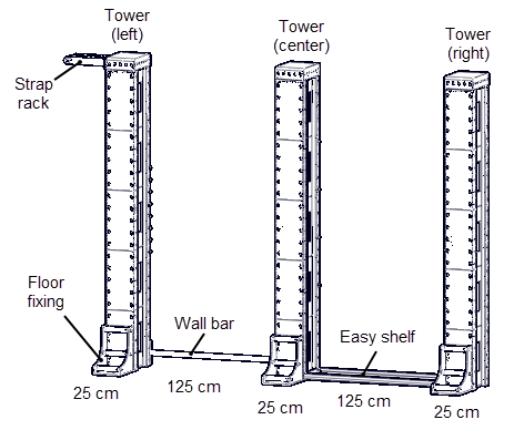
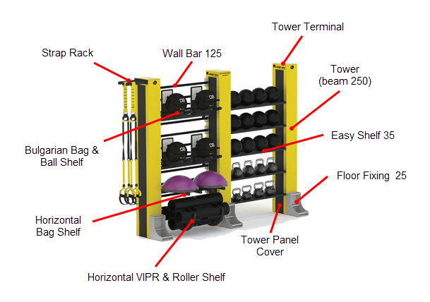
- Unpack and lay the three beam section 250 assemblies on the floor as close as possible to the install location. Refer to the rendering for specific part location and attachment information.
- Attach the strap rack to the tower terminal 35 cm side using a 6 mm hex key to secure the M10 hex key bolt, M10 flat washer, and M10 nut. Fully tighten fasteners and torque to 34 ft-lbs (46 Nm).
- Attach the assembled strap rack tower terminal to the left beam section 250 tower using a 19 mm wrench secure the M12 bolt, M12 flat washer, M12 lock washer, and M12 nut. Fully tighten all fasteners and torque to 58 ft-lbs (79 Nm)
- Attach the remaining two tower terminals on the center and right beam section 250 towers. Using a 19 mm wrench fully tighten all fasteners and torque to 58 ft-lbs (79 Nm)
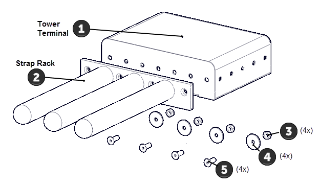
| ID | Qty | PN | Description |
|---|---|---|---|
| 1 | 1 | Q2017PFY-101 | TOWER TERMINAL 10,PF YELLOW |
| 2 | 1 | Q40728-101 | STRAP RACK |
| 3 | 4 | CWKFCN010-008 | NUT,LOCK,FULL,M10,NYLON INSERT,STL,CZ |
| 4 | 4 | CWWNCN010-025 | WASHER,FLAT,STEEL,METRIC,M10 X 40 OD X 2.5T, CZ |
| 5 | 4 | CWCNCN010-030 | SCREW,FHC,M10X1.5X30,STL,CZ |
| Note: Part qty on a per unit basis. | |||
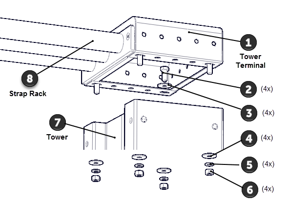
| ID | Qty | PN | Description |
|---|---|---|---|
| 1 | 1 | Q2017PFY-101 | TOWER TERMINAL 10,PF YELLOW |
| 2 | 4 | CWHMCN012-030 | SCREW,HHC,M12X1.75X30,STL,CZ |
| 3 | 4 | CWWNCN012-025 | WASHER,FLAT,STEEL,METRIC,M12 X 36 OD X 2.5T, CZ |
| 4 | 4 | CWWNCN012-025 | WASHER,FLAT,STEEL,METRIC,M12 X 36 OD X 2.5T, CZ |
| 5 | 8 | CWWBWCN012-023 | WASHER, SPLIT, M12 X 2.3MM THICK, CZ |
| 6 | 8 | CWKARCN012-010 | NUT,PLAIN,HEX,M12,STL,CZ, DIN 934 |
| 7 | 1 | Q2275PFY-101 | ASSY,BEAM,SECTION,250 S 2.0,PF YELLOW |
| 8 | 1 | Q40728-101 | STRAP RACK |
| Note: Part qty on a per unit basis. | |||
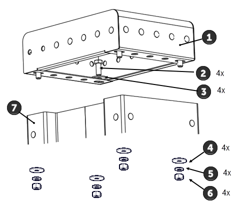
| ID | Qty | PN | Description |
|---|---|---|---|
| 1 | 1 | Q2017PFY-101 | TOWER TERMINAL 10,PF YELLOW |
| 2 | 4 | CWHMCN012-030 | SCREW,HHC,M12X1.75X30,STL,CZ |
| 3 | 4 | CWWNCN012-025 | WASHER,FLAT,STEEL,METRIC,M12 X 36 OD X 2.5T, CZ |
| 4 | 4 | CWWNCN012-025 | WASHER,FLAT,STEEL,METRIC,M12 X 36 OD X 2.5T, CZ |
| 5 | 8 | CWWBWCN012-023 | WASHER, SPLIT, M12 X 2.3MM THICK, CZ |
| 6 | 8 | CWKARCN012-010 | NUT,PLAIN,HEX,M12,STL,CZ, DIN 934 |
| 7 | 1 | Q2275PFY-101 | ASSY,BEAM,SECTION,250 S 2.0,PF YELLOW |
| Note: Part qty on a per unit basis. | |||
- Attach the floor fixing 25 to the 25 cm side of the tower for all three towers. Secure using a 6 mm hex key and 17 mm wrench to tighten the M10 hex key bolt, M10 flat washer, M10 lock washer, and M10 nut. Fully tighten all fasteners and torque to 34 ft-lbs (46 Nm). Note that the strap rack is attached on the left side of the tower, see rendering for specific attachment location.
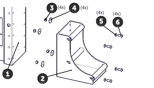
| ID | Qty | PN | Description |
|---|---|---|---|
| 1 | 1 | Q2275PFY-101 | TOWER - YELLOW |
| 2 | 4 | Q2052QMS-101 | FLOOR FIXING 25, SILVER |
| 3 | 4 | CWKFCN010-008 | NUT,LOCK,FULL,M10,NYLON INSERT,STL,CZ |
| 4 | 4 | CWWNCN010-025 | WASHER,FLAT,STEEL,METRIC,M10 X 40 OD X 2.5T, CZ |
| 5 | 4 | CWWKCN010-019 | WASHER, FLAT, STEEL, METRIC, M10 X 1.9MM THICK, CZ |
| 6 | 4 | CWTECN010-030 | SCREW,BHC,M10X1.5X30,CZ |
| Note: Part qty on a per unit basis. | |||
Anchor the towers to the floor
- Use the rendering to layout and mark the location for the left, center, and right tower floor fixing assemblies. Make sure that the unit layout provides sufficient unobstructed area around the top and sides of the equipment for installation and use.
- Precisely stand and position the three tower floor fixing assemblies per the rendering specification. Set the towers 125 cm apart. You can use a wall bar 125 and easy shelf 35 to set the exact spacing between the left, center, and right towers respectively. Make sure the three towers are positioned equal distance from the wall and square relative to each other.
- Verify that the customer approves the unit location. Always receive customer approval before doing any floor covering alterations or drilling of the anchor fastener holes.
|
|
IMPORTANT: Do not make any alterations to the flooring or drill any anchor bolt holes before verifying location with the customer. |
- Floor covering installations only: Remove the floor covering from underneath each tower. Precisely trace the outline of the tower with the floor fixing attached. Then carefully cut and remove the flooring. Replace the tower back into the final position. Repeat for each tower.
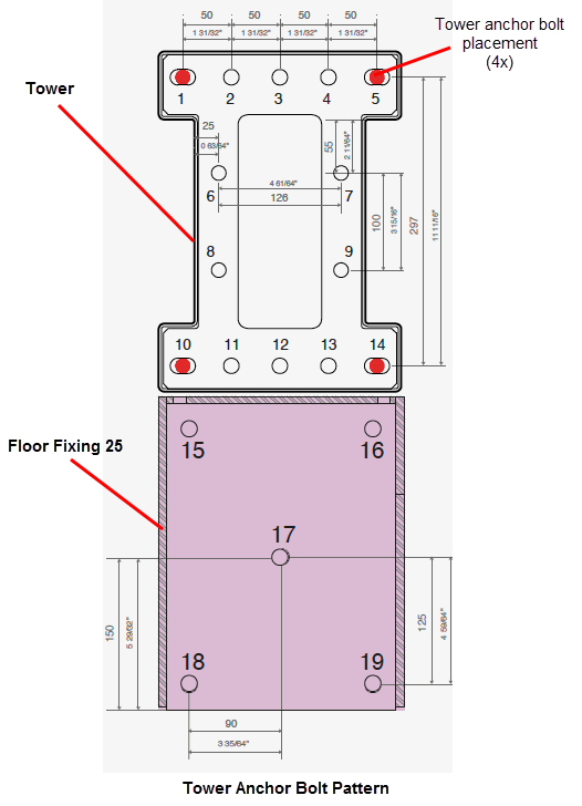
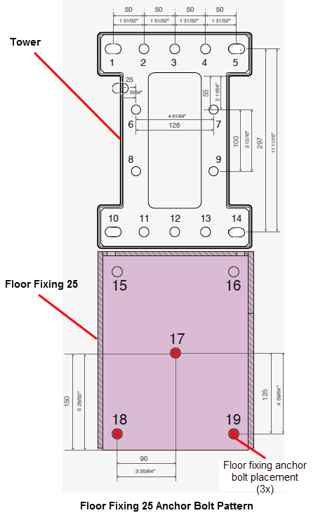
- Mark the four anchor bolt positions located on inside of the tower footplate, refer to the Tower Anchor Bolt Pattern diagram below for anchor bolt location information. Do not mark the floor fixing anchor locations at this step.
|
|
WARNING: The equipment towers and floor fixings must be installed directly on the concert surface. Any floor coverings must be removed from underneath the towers and floor fixings. Floor coverings can cause premature loosening of fasteners causing possible hardware failure and harm to exercisers. |
|
|
IMPORTANT: Before anchor bolt installation read the Floor Anchoring Requirements topic (see Floor Anchoring Requirements). Only use the Precor approved anchor bolt types (see Approved anchor bolt types) and adhere to the anchor bolt installation depth and position instructions (see Anchor bolt installation Summary). |
- Move the towers from the install location. Then use the marked tower anchor bolt locations to drill and install the anchor bolts for the left, center, and right towers. The size of the anchor hole and depth will depend on the type of anchor used, refer to Approved anchor bolt types and Anchor bolt installation Summary for more information.
|
|
WARNING: Review the site survey prior to ANY drilling and make sure that there are no conditions or obstacles (such as electrical conduit, post-tension rebar, etc.) that could cause personal or facility damage while drilling. |
- Mount the left, center, and right towers onto the anchor bolts and secure using the anchor bolt washer and nut. Snug but do not fully tighten the anchor fasteners at this step.
|
|
TIP: Snug fasteners, do not fully tighten fasteners at this step. |
Install the Tower Placards
- At this stage in the process you will need to Install the tower placards. Refer to the placards, labels, and decals installation document included with the literature kit materials shipped with the unit for placement information.
Install the Wall Bars
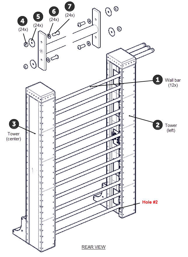
- Install the twelve wall bar 125s between the left and center towers as shown on the rendering. Secure using the M10 hex key bolt, M10 lock washer, M10 flat washer, and M10 nut fasteners. Fully tighten all fasteners and torque to specification 34 ft-lbs (46 Nm). Fastener hardware included in box with part,
| ID | Qty | PN | Description |
|---|---|---|---|
| 1 | 3 | Q40022-101 | WALL BAR 125,BOX OF 4 |
| 2 | 1 | Q2275PFY-101 | TOWER - LEFT |
| 3 | 1 | Q2275PFY-101 | TOWER - RIGHT |
| 4 | 48 | CWKFCN010-008 | NUT,LOCK,FULL,M10,NYLON INSERT,STL,CZ |
| 5 | 48 | CWWNCN010-025 | WASHER,FLAT,STEEL,METRIC,M10 X 40 OD X 2.5T, CZ |
| 6 | 48 | CWWKCN010-019 | WASHER, FLAT, STEEL, METRIC, M10 X 1.9MM THICK, CZ |
| 7 | 48 | CWTECN010-030 | SCREW,BHC,M10X1.5X30,CZ |
| Note: Part qty on a per unit basis. | |||
Install the Easy Shelf 35s
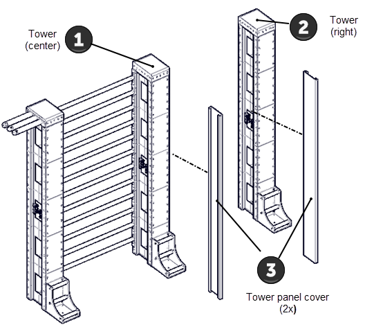
- Install the center tower - right side tower panel cover and the right tower - left side tower panel covers.
| ID | Qty | PN | Description |
|---|---|---|---|
| 1 | 1 | Q2275PFY-101 | TOWER - CENTER |
| 2 | 1 | Q2275PFY-101 | TOWER - RIGHT |
| 3 | 2 | Q40035-125 | BEAM PANEL COVER125CM |
| Note: Part qty on a per unit basis. | |||
- Install the five easy shelf 35s between the center and right towers as shown in the rendering. Secure using the M10 bolt, M10 lock washer, M10 flat washer, and M10 nut. Fully tighten and torque to specification 34 ft-lbs (46 Nm).
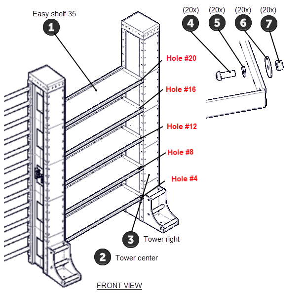
| ID | Qty | PN | Description |
|---|---|---|---|
| 1 | 1 | Q40704-101 | WLDMT,EASY SHELF 35 |
| 2 | 1 | Q2275PFY-101 | TOWER - CENTER |
| 3 | 1 | Q2275PFY-101 | TOWER - RIGHT |
| 4 | 48 | CWTECN010-030 | SCREW,BHC,M10X1.5X30,CZ |
| 5 | 48 | CWWKCN010-019 | WASHER, FLAT, STEEL, METRIC, M10 X 1.9MM THICK, CZ |
| 6 | 48 | CWWNCN010-025 | WASHER,FLAT,STEEL,METRIC,M10 X 40 OD X 2.5T, CZ |
| 7 | 48 | CWKFCN010-008 | NUT,LOCK,FULL,M10,NYLON INSERT,STL,CZ |
| Note: Part qty on a per unit basis. | |||
Anchor the Floor Fixings to the floor
- Install the floor fixing anchor bolts:
- Remove the floor fixing front mini bar 25 to gain access to the front anchor bolt holes. Retain part(s) and/or fastener(s) for installation.
- Drill the three floor fixing anchor bolt holes per the floor fixing 25 bolt pattern diagram shown below. The anchor bolt holes must be drilled perpendicular to the concrete surface. Drill the anchor bolt holes per the manufacturers instructions, review Floor Anchoring Requirements.
- Install the three anchor bolts and secure using the washer and nut. Fully tighten each floor fixing anchor bolt and torque to specification 37 ft-lbs, (50 Nm).
- Fully tighten the four tower anchor bolt and torque to specification 37 ft-lbs, (50 Nm).
- Reinstall the front floor fixing front mini bar 25s and fully tighten fasteners.
- Repeat the anchor bolt installation process for each tower.
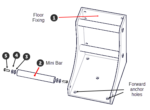
| ID | Qty | PN | Description |
|---|---|---|---|
| 1 | 1 | Q40411-101 | WLDMT,FLOOR FIXING 25,SILVER |
| 2 | 1 | Q40052-101 | MINI WALL BAR |
| 3 | 2 | CWWKCN010-019 | WASHER, FLAT, STEEL, METRIC, M10 X 1.9MM THICK, CZ |
| 4 | 2 | CWWBWCN010-020 | WASHER, SPLIT LOCK, M10 X 2.0MM THICK, CZ |
| 5 | 2 | CWTECN010-035 | SCREW,BHC,M10X1.5X35,CZ |
| Note: Part qty on a per unit basis. | |||
Install remaining panels
- Install the four remaining tower panel covers on the left, center, and right towers. Secure using either the panel clips or the fixing carter bars with elastic band.
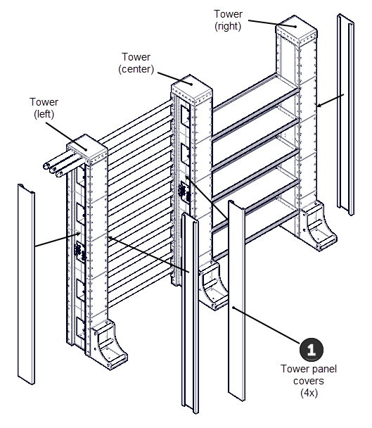
| ID | Qty | PN | Description |
|---|---|---|---|
| 1 | 4 | Q40035-125 | BEAM PANEL COVER125CM |
| Note: Part qty on a per unit basis. | |||
Install the Unit Optionals
- Install the unit Optionals. Use the rendering to determine the installation locations for the unit optionals.
- Assemble and Install the Horizontal VIPR & Roller Shelf optional. see Horizontal VIPR & Roller Shelf Optional Assembly .
- Assemble and install the Bulgarian Bag and Ball optional, see Bulgarian Bag and Ball Optional Assembly.
- Assemble and Install the Horizontal Bag Shelf optional, see Horizontal Bag Shelf Optional Assembly.
Install Placards, Labels, and Decals
- Apply any remaining placards, labels, and decals shipped with the unit. Refer to the placards, labels, and decals installation document included with the literature kit materials shipped with the unit for placement information.
See Also