Drive Roller Replacement
About
This procedure provides instruction to remove and replace the Drive Roller.
|
|
CAUTION: Two running belt gauges, Precor part number 20007-101, are required. It is important that this procedure be followed to maintain correct drive belt and running belt tension. Improper tensioning of the belt will lead to premature running belt wear, premature driver roller bearing failure and premature Take‑Up roller bearing failure. |
Procedure
Review entire procedure before starting.
- Switch the input power OFF and unplugDisconnect a device power cord plug or cable connector from the power receptacle or outlet. the power cord.
- Remove the front hood.
-
Relax the running belt tension by alternately loosening the left and right Take‑Up roller mounting/adjustment bolts, but do not remove the mounting bolts.
-
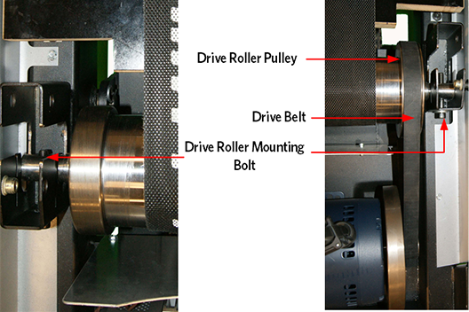
Walk the drive belt off the smaller drive motor pulley. Remove pulley off the drive roller pulley.
-
Alternately loosen and remove the left and right drive roller mounting bolts.
|
|
TIP: Before loosening the mounting bolts, you can put a reference mark on the right drive roller mounting bracket to identify the current drive roller shaft position used later for re installation. |
- Use the drive belt to help lift the roller out of the mounting bracket and then remove the belt off the drive roller pulley,
- Remove the drive roller.
-
Insert the replacement drive roller through the running belt. Use running belt to help lower and slide the drive roller into the mounting bracket.
- Insert the replacement drive roller through the running belt. Place the drive belt onto the drive roller pulley and use the drive belt to help lower and slide the drive roller into the roller mounting bracket. Hand tighten the left and right drive roller mounting bolts.
-
Position the running belt on the rollers so that it is centered and sets square on the deck from the front drive roller to the rear Take‑Up roller.
-
Alternately tighten the left and right drive roller mounting bolts to evenly tighten the roller until the left mounting bolt reaches the left mount stop. The left mounting bracket stop sets the roller reference position and the right bolt is used to make final position adjustments. Fully tighten the left mounting bolt against the bracket stop position.
-
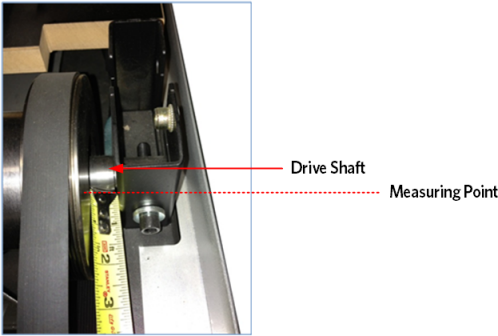
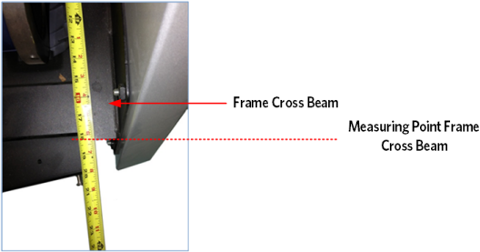
Using a measuring tape, measure the distance from the front of the left drive roller shaft to the front of the frame cross beam. Record this reference distance.
-
Adjust the right drive roller mounting bolt so that the right drive roller shaft to frame cross beam distance equals the left side reference distance. This adjustment will make sure that the drive roller is positioned parallel and square to the front of the frame.
-
Install the drive belt onto the drive motor pulley and walk the drive belt onto the larger drive roller pulley.
-
Verify the drive belt alignment and set tension to specification, see Drive Belt Tension & Alignment Adjustment procedure.
-
Set the running belt tension to specification and verify tracking, see Running Belt Tension and Tracking Adjustment procedure.
-
Replace the belt guard cover ensuring the tabs are firmly locked into position on the Take‑Up roller shaft (see End Cap & Belt Guard Cover Replacement).
-
Replace the end cap (see End Cap & Belt Guard Cover Replacement).
- Replace the hood cover.
Installing the drive roller
- Verify treadmill operation (see ) and return to service.
.See Also