Drive Motor Replacement
About
This procedure provides instruction to replace the Drive Motor.
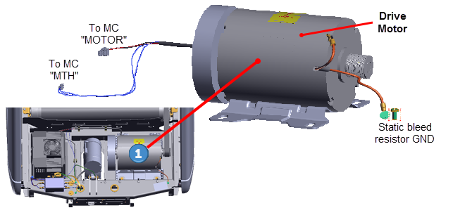
The Drive Motor is located in the Drive Motor compartment at the front of the treadmill under the hood cover.
| ID | Description |
|---|---|
|
|
Drive Motor |
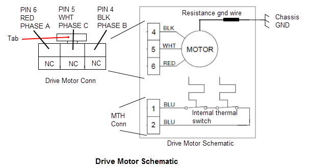
Drive Motor Cable Schematic
Procedure
Review entire procedure before starting.
Removal Instructions
- Switch the power OFF and unplugDisconnect a device power cord plug or cable connector from the power receptacle or outlet. the power cord.
- Remove the hood cover, see Hood Cover Replacement.
-
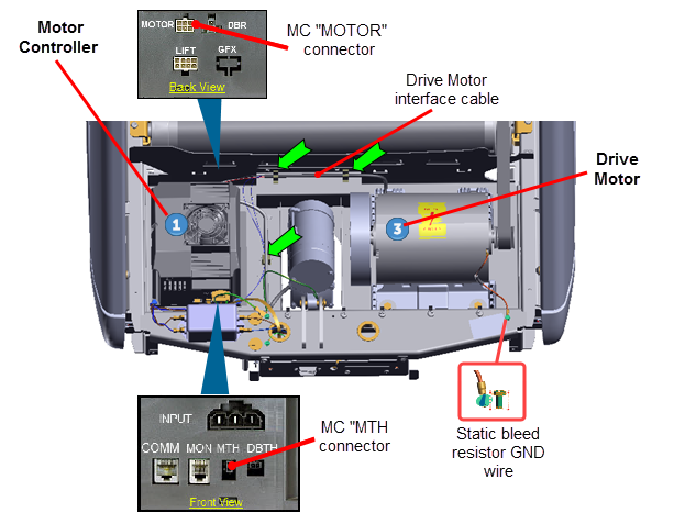
Disconnect the Motor Controller "MTH" and "MOTOR" electrical connections:
- Remove the MCMotor controller or motor controller module base from the mounting fasteners to allow connector access, see Motor Controller (MC) Replacement.
- Disconnect the MC "MTH" and "MOTOR" interface cable connectors, see Motor Controller (MC) Replacement.
- Remove the motor interface cable from the three frame cable clamps.
- Use a 5/16" socket (or nut driver) to remove the Drive Motor static bleed resistor ground wire (Orange wire). Retain part(s) and/or fastener(s) for installation.
- Use tape or marker to make a motor base position reference mark. This reference mark will be used to help position the replacement motor installation position.
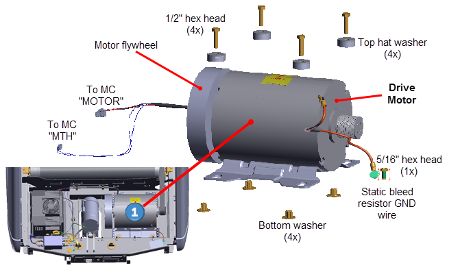
- Remove Drive Belt tension by loosening the four Drive Motor
 1/2" hex head fasteners. Remove the Drive Belt by walking the belt off the Roller pulley and then the motor pulley.
 - Remove the four 1/2" hex head bolts, plastic top hat washers, and bottom washers fastener hardware. Remove the drive motor. Retain part(s) and/or fastener(s) for installation.
Installation Instructions
-
Install the replacement Drive Motor into the motor isolation tray and secure using the four 1/2" hex fasteners, plastic top hat washers, and bottom washers fastener hardware.
- If you made a motor base install reference mark prior to removal, adjust the Drive Motor base position to the motor base install reference mark and fully tighten the four 1/2" hex head fasteners
- If you did not make a motor base install reference mark prior to removal, position the motor base to the rear tab stops (minimum belt tension position) and fully tighten the four 1/2" hex head fasteners.
- Reconnect the motor static bleed resistor ground wire and secure using the 5/16 " hex head fastener. Fully tighten the fastener to ensure good electrical contact with the frame weldment.
|
|
WARNING: Static electric shock hazard. Make sure the motor static bleed resistor ground wire is securely connected to the frame. When the ground wire is not connected, touching the motor housing could cause static charge electrical shock and personal injury. |
- Reconnect the Motor Controller "MTH" and "MOTOR" cable connectors , see Motor Controller (MC) Replacement. Make sure the cable connectors have the correct orientation and alignment before inserting into the MC I/OInput and Output Interface. connector.
|
|
CAUTION: Take your time and be careful when reconnecting the MC cable connectors. Many of the connector contacts are small and can be easily damaged if incorrectly inserted into the MC connector. |
- Reinstall the MC by sliding the left side base flange under the two left preinstalled loosened fasteners. Then install the two right side fasteners and fully tighten all four 1/2" hex fasteners, see Motor Controller (MC) Replacement.
- Route cables and secure using the three frame cable clamps. Recheck all cable MC connections and make sure that the cables have freedom of movement and clear of any frame or component edges that could pinch or damage the cable wires.
- Reinstall the drive belt. Place the Drive Belt onto the Roller pulley and walk the belt onto the Drive Motor pulley.
|
|
TIP: Use (turn) the Drive Motor flywheel to make it easier to turn the motor pulley and help walk the belt onto or off the Drive Motor and Drive Roller pulleys. |
- Connect the power cord and switch the power ON.
- Verify the Drive Belt alignment and tension to specification. see Drive Belt Tension and Alignment Adjustment.
- Reinstall the hood cover, see Hood Cover Replacement.
- Do the Operation Verification tests (see Operation Verification) and return to service.