Lift Motor Replacement
About
This procedure provides instruction to remove and replace the Lift Motor.
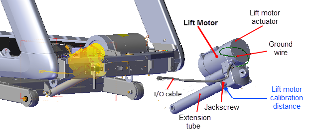
Specification
| System Component | Specification |
|---|---|
| Lift Motor Calibration Distance* | 1 1/8 in - 1 3/16 in (2.8 cm - 3.0 cm) |
| Note: * Calibration distance is specified at incline level 0. | |
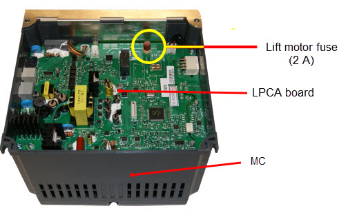
Lift Motor Fuse
he lift motor fuse (2 Amp) is located on the LPCALower printed circuit assembly; generally this refers to the lower board. On treadmills, this is the motor controller unit (MCU), and on self-powered units, it is the main board in the lower section. board in the MCMotor controller or motor controller module module. Remove the MC bottom cover to access the fuse. Use a small standard screwdriver to unsnap the clip fasteners and remove the cover.
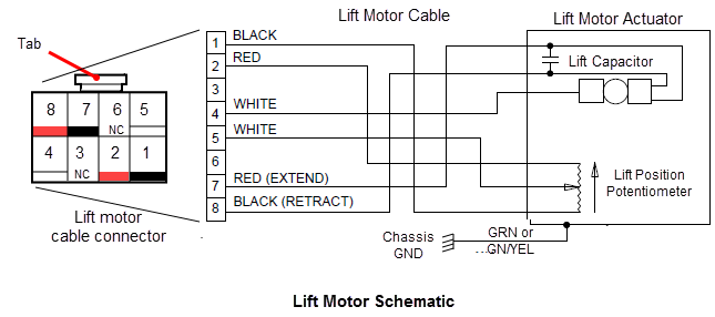
Lift motor cable schematic
Procedure
Removal Instructions
Review entire procedure before starting.
- Remove the hood cover, see Hood Cover Replacement.
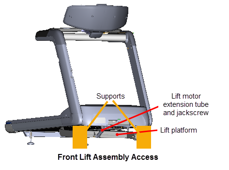
- You can access the lift motor jackscrew in one of two methods: 1) by raising the treadmill providing access from the front of the treadmill or 2) by laying the treadmill on its side. This procedure uses the front access method. If you do not have supports available, then use the alternative side access method, see Side lift platform assembly access procedure.
|
|
Note: You can also access the jackscrew by laying the treadmill on its side, see Side lift platform assembly access procedure. |
- Access the service menu (51765761) and select INCLINE TEST. Use the incline control to set the incline level to 14.
- Securely and safely place supports (e.g. car jack stands) under the left and right front corners of the frame weldment.
- Slowly lower the incline level in 0.5 increments until the complete weight of the frame is setting on the supports. Verify the supports are stable and secure carrying the weight of the treadmill. Continue lowering the incline level to "0". Incline level "0" is the lift motor calibration reference incline level.
|
|
IMPORTANT: Its important to set the incline level to "0" (calibration ref level) before switching the power OFF. |
- Switch the power OFF and unplugDisconnect a device power cord plug or cable connector from the power receptacle or outlet. the power cord.
- Disconnect the lift motor interface cable from the MC "LIFT" connector. Remove the interface cable from the cable routing clamp.
|
|
TIP: Remove the MC fasteners so that the MC module can be raised to allow easy access to disconnect and connect the I/OInput and Output Interface. connectors. |
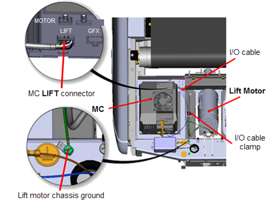
- Remove the lift motor ground wire (GRN or GRN/YEL) from the frame chassis ground screw fastener.
- Remove the extension tube hitch pin and clevis pin fastener hardware from the lift platform mounting bracket. Hold the lift platform while removing the clevis pin and carefully rest on the floor.
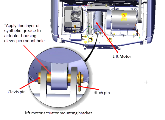
- Remove the lift motor actuator housing mount hitch pin and clevis pin fastener from the frame pan mounting bracket. Hold the lift motor while removing fasteners and carefully remove from the treadmill.
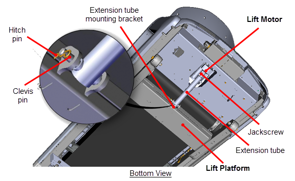
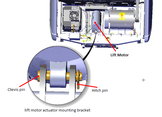
Installation Instructions
Lift motor calibration
- Lay replacement lift motor on the floor in front of treadmill. Connect the the lift motor interface cable to the MC "LIFT" connector.
- Connect the power cord and switch the power from OFF to ON. This will set the lift motor to the calibration reference incline level "0".
- Switch the power OFF and unplug the power cord.
- Disconnect the MC "LIFT' connection.
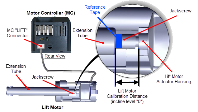
- Firmly hold the jackscrew and rotate the extension tube to adjust the calibration distance. The calibration distance is measured between the top of the extension tube nut and the lift motor actuator housing. Adjust the calibration distance to specification between 1 1/8 in - 1 3/16 in (2.8 cm - 3.0 cm).
|
|
IMPORTANT: Make sure the extension tube does not rotate after setting the calibration distance. Use tape to mark the extension tube position on the jackscrew. |
- Clean and apply a thin layer of synthetic grease to the inside of the lift motor actuator housing clevis pin mounting hole . Then install the pre-calibrated lift motor placing the treadmill actuator housing mount into the frame pan mounting bracket. Secure using the clevis pin and hitch pin.
- Place the extension tube into the lift platform mounting bracket and secure using the hitch pin and clevis pin. It may be necessary to slightly rotate the extension tube to align the clevis pin mounting holes. Choose an adjustment direction that will minimize the change to the extension tube calibration distance. Firmly hold the jackscrew from turning while adjusting (rotating) the extension tube.
- Connect the lift motor I/O cable MC "LIFT" connector. Route cable and secure in the frame routing cable clamp. Connect the ground wire (GRN or GRN/YEL) to the chassis ground screw and fully tighten.
-
If the MC was loosened or removed, install the MC and secure fasteners, see Motor Controller (MC) Replacement.


Remove blocking and lower treadmill
|
|
Note: If you used the side access method, then refer to the "Side lift motor jackscrew access" procedure to upright the treadmill, see Side lift platform assembly access. |
- .Connect the power cord and switch the power ON. Be aware that switching the power ON will cause the incline platform to move and return to the level "0" position.
|
|
WARNING: Keep hands and appendages clear of the incline platform assembly before switching power ON. Switching power ON will cause the incline platform to move to the level "0" Home position. |
- Access the service menu (51765761) and select the INCLINE TEST. Increase the incline level enough to lift the treadmill frame off the supports.
- Remove the supports and clear any other items that might either block the treadmill from lowering or may be damaged as it lowers.
- Lower the incline to level "0".
- Reinstall the hood cover, see Hood Cover Replacement., .
-
Verify the treadmill incline operation from minimum to maximum levels.Make sure that there are no active Incline function related error codes.
- Do the Operation Verification tests (see Operation Verification) and return to service.