Incline Lift System Troubleshooting
The incline Lift system consists of an ACAlternating Current: electric current which periodically reverses direction between positive and negative polarity. voltage driven lift motor (120 Vac or 240 Vac) and an internal 1 K ohm potentiometer for lift position monitoring.
The first step in troubleshooting the lift system is to review the error log for any lift system error codes. Then determine whether the problem is related to a lift movement issue or a lift position sensor issue. If the lift does not move, then the problem is most likely related to defective lift motor windings or the MCMotor controller or motor controller module lift motor control circuitry. if the issue is with the lift platform position, then most likely the issue is due to a defective lift position sensor potentiometer.
Use the lift motor related error codes 40 thru 45 to help isolate and repair the fault.
Related Error Codes
| RELATED ERROR CODE |
DESCRIPTION |
|---|---|
| 40 | No Lift Motion Detected |
| 42 | Lift Position Out Of Range |
| 44 | Un-commanded Lift Motion |
| 45 | Lift Moving In the Wrong Direction |
Troubleshooting Procedure
Error code events are generated when the lift system has been commanded to move and no and/or incorrect lift motion has been detected.
Review the machine Error Log or CPATouchscreen console Control Processing Assembly. Event Log and note any lift system related error codes (codes 40 thru 45). Then use the Error Code and Troubleshooting Guide to learn about these error codes and procedures to troubleshoot and repair the issue, see Error Code Troubleshooting Guide.
Operating the lift motor for troubleshooting
In normal operating mode, the treadmill requires the running belt to be moving to operate the lift. Therefore, it is recommended to operate the lift motor from the service Hardware Validation > Machine Test > Incline Test diagnostic test (see Hardware Validation Diagnostics Tests Menu (51765761)) .
The Incline Test diagnostic test will allow the incline to be changed without the running belt movement requirement. The Incline Test also allows lift incline control during an out-of-range lift position fault. This allows recovery from an out-of-range fault condition.
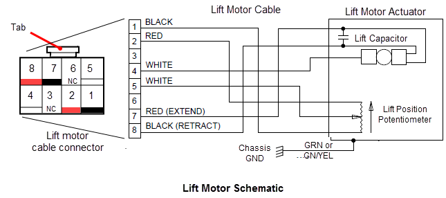
Lift motor schematic
Procedure
- Switch the input power OFF. Visually inspect the lift motor cable wires for damage (torn insulation, bare wires, shorted/open wires, etc.) and MC module I/OInput and Output Interface. connectors for any damaged pins, shorted pins, or improperly crimped connections.
- Switch the power ON. Verify the lift system operation, If there are still faults with the lift system, continue procedure.
- Review the Error Log and record any current and past lift system error codes. Then use the Error Code Troubleshooting Guide (see Error Code Troubleshooting Guide) to isolate and resolve the fault condition.
- Along with the Error Code and Troubleshooting Guide, review the following supplemental information to help troubleshoot and resolve any failures.
Additional Information
Use the following additional troubleshooting information along with the Error Code and Troubleshooting Guide to help troubleshoot and resolve any failures
Error Code 40 "NO Lift Motion Detected"
Use the Error Code Troubleshooting Guide (see Error Code Troubleshooting Guide) for troubleshooting and repair information.
Possible Fault Causes:
- Lift motor cable connector pins damaged or not properly seated (plugged in)
- Damaged lift motor windings.
- Lift platform is physically jammed and unable to move.
- Lift fuse is blown (open).
- Bad MC lift motor control circuitry.
- Check for damaged lift motor cable wiring and/or connectors:
Inspect the lift motor cable wires and connector pins for damage which could cause an open or short circuit condition. Make sure the cable connector is properly connected and seated to the MC LIFT connector. Test the incline lift system operation. if the lift system does not correctly operate, continue procedure.
-
Switch the input power OFF. Disconnect the MC LIFT connector. With an ohmmeter, measure between terminals 5 (white) & 1 (black) and 5 (white) & 2 (red) of the lift motor cable LIFT connector. Both readings should be approximately 12 ohms for a 120VAC lift motor and approximately 24 ohms for a 240 VACvoltage in an alternating current circuit lift motor. If either reading is significantly high or open replace the lift motor
- Disconnect the lift motor tube from the lift platform. If the lift platform is jammed, disconnect the lift motor from the lift platform. If the lift tube or lift nut is jammed against the motor housing, rotate the lift nut or lift tube away from the motor housing:
- If the lift motor was jammed, make sure the lift fuse is good. Do the Check for a blown lift motor fuse step.
- If the lift motor was jammed, recalibrate the lift motor and reinstall the lift motor into the lift platform, see Lift Motor Calibration.
- Verify the lift movement and operation. if there are remaining lift motor fault conditions, continue procedure.
- Check for a blown lift motor fuse:
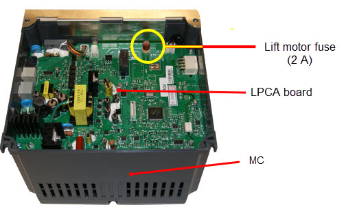
- Remove the MC, see Motor Controller (MC) Replacement.
- The lift motor fuse (2 Amp) is located on the LPCALower printed circuit assembly; generally this refers to the lower board. On treadmills, this is the motor controller unit (MCU), and on self-powered units, it is the main board in the lower section. board in the MC module. Remove the MC bottom cover to access the fuse. Use a small standard screwdriver to unsnap the clip fasteners and remove the cover.
- Remove the fuse and use a multimeter to measure the resistance across the fuse leads. The resistance will read almost zero ohms for a good fuse. any high or infinite resistance reading indicates the fuse is bad (open circuit).
- Replace the fuse if bad. Switch the power ON. If the fuse immediately blows after power up, troubleshoot the issue causing the blown fuse including: lift motor cable wires or connector pins short circuiting (inspect cable), a short circuited lift motor capacitor (see Verify the lift motor capacitor step), or a bad MC lift switch can cause the lift platform to jam which in turn can cause a blown lift fuse (see Lift motion in only one direction step).
-
Verify the lift motor capacitor.
The lift capacitor is mounted inside the lift motor. If the lift capacitor is shorted, the lift fuse will blow (open). If the lift capacitor is leaky, it may work for lighter people and not for others. If the lift capacitor is open, the lift platform will not move.- Shorted lift motor capacitor test: Disconnect the lift motor connector from the MC and using an ohmmeter measure between pins 7 (red) 8 (Black) of the lift motor connector. If the resistance is 0 ohms, replace the lift motor.
- Leaky or Open lift motor capacitor test: Connect the lift motor cable connector to the MC. With the incline below 15% (to allow room for lift travel), measure the AC voltage between pins 7 (red) and 8 (Black) of the lift motor connector. Select the manual running program and press the INCLINE UP control. The AC voltmeter should momentarily read between 1.5 to 2.0 times the AC line voltage. If this reading is significantly low, replace the lift motor. Note that the AC line voltage reading will only be present for a short period before an error condition is displayed
- Lift motion in only one direction:
A failed MC lift switch or failed lift motor winding can cause this failure.- A shorted MC lift switch will cause uncommanded UP or DOWN lift movement as soon as the machine is powered up. Typically this fault will cause the lift platform to be jammed and it will also probably cause the MC lift fuse to blow. If the lift moves as soon as the power is turned on and eventually jams, the MC must be replaced. Refer to error code 44 for more information.
- An open MC lift switch will cause the lift to only move in one direction. Perform the following steps to determine if the switch is open:
- Move the incline below 15% to allow room for lift upward travel. Disconnect the MC LIFT connector and connect an AC voltmeter between terminals 4 (white) & 7 (red) of the MC LIFT connector (see lift motor schematic). Select the manual program mode and press the INCLINE UP control. The AC voltmeter should read AC line voltage (either 120VAC or 240VAC). Note that the AC line voltage reading will only be present before an error condition is displayed. A correct reading verifies that the lift UP switch is working properly. If the UP switch test failed, replace the MC.
- Move the incline above 80% to allow room for lift downward travel. Connect an AC voltmeter between terminals 4 (white) & 8 (black) of the MC LIFT connector. Set the treadmill in the manual program and press the INCLINE DOWN control. The AC voltmeter should read the AC line voltage (either 120VAC or 240VAC). Note that the AC line voltage reading will only be present before an error condition is displayed. A correct reading verifies that the DOWN switch is working properly. It the DOWN lift switch test fails, replace the MC.
- If the MC lift switch is good, then the lift motor winding is bad. The lift will not operate in one or both UP/DOWN directions depending on the exact fault in the motor, replace the lift motor.
- If the lift system does not work after performing the previous troubleshooting tests, remove the bad lift motor and place on the floor in front of the treadmill. Substitute a known good lift motor. Make sure the MC Lift fuse is good and then verify incline operation.
- If the good lift motor works, replace the original bad lift motor.
- If the good lift motor does no work. replace the MC module.
|
|
CAUTION: Do NOT substitute MC modules or the replacement MC could be damaged. |
See Also
System Troubleshooting Procedures